‘BIG BERTHA‘
A SCRATCHBUILT ARTILLERY PIECE
In 1/76 Scale
BY KEN MUSGRAVE
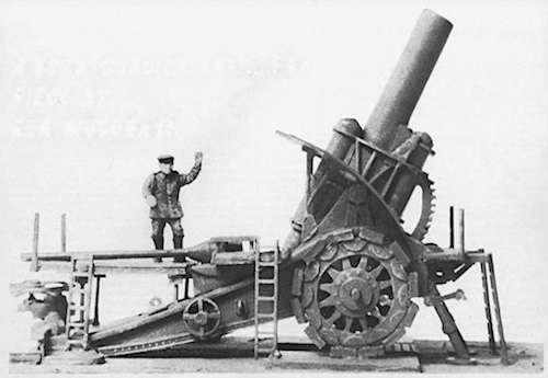
FORESEEING the need for heavy artillery capable of demolishing concrete fortifications in any future war, the German Army in 1908 asked for a howitzer of 42 cm. calibre and a shell weight of 2100 lbs. The designers and ballistic experts at Krupps of Essen quickly got down to the task and by 1911 they had produced a gun ready for test firing and which proved to be exceptionally accurate at a range of 16000 yards. Difficulties with the shell design concerning the packing of the high explosive were eliminated until, eventually, a standardised shell weight of 1150 kg. was established.
The army, however, wanted the howitzer to be capable of being transported by road and a re-design was initiated aimed at lightening the weapon which weighed in at the enormous total of 175 tons. This involved shortening the barrel length by two calibres and thereby reducing the range to a maximum of 10250 yards and firing a shell weighing 1800 lbs. The object of the exercise had however been achieved and the howitzer, n0w weighing nearly 43 tons, could now be broken down into five separate loads and towed by Daimler-Benz tractors; the days of the Liege forts were now numbered! Although not much pictorial or dimensional information is readily available about this interesting and historically important weapon, this need not be an obstacle to building a model which is both impressive and reasonably accurate; as I have stated before in a previous article, better a model that is not wholly accurate to the last millimetre than no model at all.
The main source for my plan and model were the excellent illustrations by John Batchelor in the books Artillery, published by Macdonalds, and 1914-The Opening Moves, by John Keegan, and published by Ballantine. The historical details are from The Guns-1914-1918, by Ian Hogg, also published by Ballantine which is thoroughly recom. mended to anyone interested in the history of artillery, especially pages 36- 43 which deal specifically with the 42 cm. Howitzer and describe in detail the origins of the gun, its development and the action which took place at Liege in August 1914. A further helpful source is the Imperial War Museum photograph Q65817.
The Model
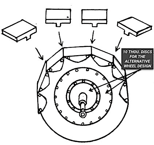
The first step in making the model was the wheels and these were cut from 40 thou. plastic sheet and the spokes cut out with the aid of various shaped needle files: an alternative style of wheel shown in the John Batchelor illustrations is much simpler and I have sketched this in Fig. 1. (These numbered sketches, by the way, are not to scale and merely an aid to clarify certain points not evident in the plan and when cutting parts to size, or length, reference should be made to the main drawing. )
Both types of wheel show heavy rivet detail which should be added before cementing the 10 thou. discs on the wheels with the point of a compass or dividers and help considerably in the finished appearance of the model. I then tackled the fitting of the twelve shoes around the rim of each wheel made from 10 thou. and at the space between the shoes stuck the square shaped pads, again twelve, made from 40 thou. sheet.
These pads were, of course, hinged on the real thing and helped the gun to be moved over soft or muddy terrain. Reference to Fig. 1 should help to clarify the construction of this particular aspect of the model. Having made the wheels, I then moved on to the trail which was a straight sided box-like structure tapering to the rear and made mainly from 30 thou. with smaller details like the hatches in 10 thou.

The sketch at Fig 2 should be of assistance in building this part and to obtain the distinctive upsweep of the trunnion side plates. Without evidence to the contrary, and I would be grateful for confirmation or otherwise, I have assumed that the handwheel situated midway on the trail side to be a brake handwheel and consequently I have put one on either side with plastic rods leading to the axles.
Finally I drilled holes at the axle and trunnion points. Fig. 3 illustrates the next section, the spade and traversing mechanism which was a huge steel casting with a toothed arc used in the sighting and pivoting of the piece; again plastic sheet of various thickness was used, the main base plate in contact with the ground being 40 thou. and the traversing drum being laminations of the same thickness.
The toothed arc is a bit fiddly but well worth the trouble, the teeth being merely small strips of 20 thou. and when touched up with silver paint in the final stage to give a used appearance look quite realistic. As indicated in the sketch the trail fits into the cutout in the spade assembly and is cemented in position. We can now turn our attention to the bed plate situated under the wheels which is quite a simple construction and should be cut from 40 thou. to the shape shown in Fig. 4, taking the width from the main plan.


The centre section of the plate was slightly thicker and a piece of 10 thou. with rivet details applied thereto completes the bed plate. At this point, with a small diorama in mind I glued the completed parts to a small base which made the handling of the model in the later stages of building much easier. The characteristically German curved shield was my next challenge; surprisingly it turned out quite simple. After cutting out the basic shape from 20 thou. I obtained the curve by pressing the edge of a ruler down onto the plastic and pulling the shield away, a method used by all modellers from the year zero but it achieved just the correct shape required. See Fig. 5 for the basic shield shape.
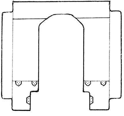
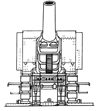
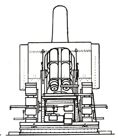
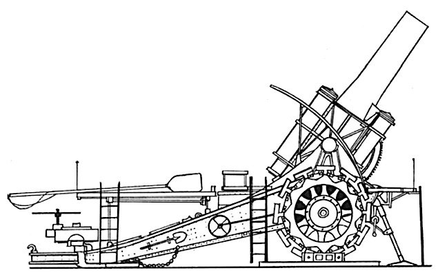
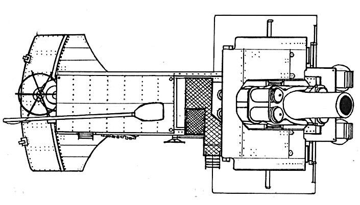
The barrel and recoil mechanism looks quite a formidable undertaking but basically the whole thing breaks down to a barrel with two recoil cylinders on top and two on the bottom with a wrap around jacket arrangement at the centre of which the whole mass pivots at the trunnion. I carved the barrel, breech and cylinders from wood and glued the top two cylinders in position. Between the barrel and the bottom two cylinders a length of 40 thou. curved on the top surface represents the recoil slide and the two bottom cylinders are cemented below slightly more forward than the top pair. Reference to Fig. 6 and the illustrations of John Batchelor should be more helpful than words in showing the construction and detailing of this stage of the model.


Finally, the various platforms and detailing of the model. The front platform appears to have been optional and is not shown in the IWM photograph but the model looks better with one and it covers up areas which are a bit obscure. The platform is positioned on the protruding portions of the trail forward of tho shield on a supporting cross girder, see Fig. 7, which also shows the position of the ladders and supporting legs.
The ladders, incidentally, are ex-model railway signal ladders and have been in my scrap box for years waiting, apparently, for just this opportunity. The. rear platforms are shown in Fig. 8, the largest one supported by four legs cut from plastic rod, and two more sections of ladder placed in their respective positions as shown in the plan and accompanying sketches. Shield supports, also from plastic rod, and rammer were added along with various figures from the Airfix WW1 German set, some with slight surgery, and the whole gu 1 was painted field grey with a dusty effect given by an almost rlry brush of white and worn areas, such as platform tops, ladders, handwheels and traversing gear, were dry brushed with silver.

Fig. 8
When painting the base I had it in mind to depict the Liege action, it was the early days of August 1914 when the countryside was still untouched by the war and so I painted it accordingly; however, during the bombardment of the forts the howitzers were actually moved into the town of Liege and fired from one of the squares! One could therefore quite legitimately show the base as a flat area of roadway or pave possibly surrounded by buildings, presumably in various states of collapse.
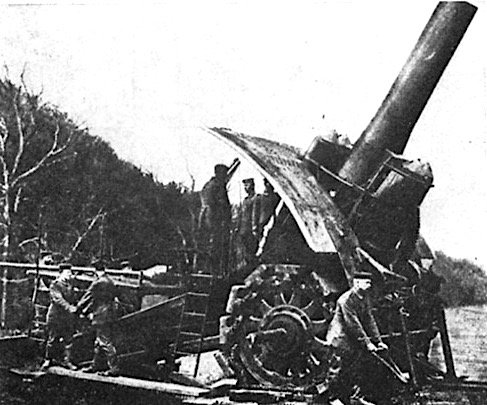
The German 42 cm ( 16.5″) “Big Bertha” howitzer was the result of much research in the field of large steel castings by Krupp. The gun evolved slowly from a 30.5 cm coast mortar, then a 240 mm model. Code named “Gamma”, Big Bertha ( named after Bertha Krupp von Bohlen und Halbach) and her sister howitzers made short work of the Liege Forts on August 12t1914. Photo: Imperial War Museum.
Ref. Q.65817.
Reproduced by kind permission from Doolittle Media

