A DIY and Portable Model Makers Workshop…..In a BOX?
Planning to make a model making workshop is fun. When it becomes a priority because there is little to no room for a permanent set-up it can suddenly become quite urgent! My requirements were simple, portable, big on the inside but small on the outside….Dr. Who fans need not worry as I was not about to mess with Time And Relative Dimensions In Space!
The HobbiBox ™
I had decided to get back into the model making hobby after many years absence, but it became quickly apparent, that after amassing some of the basic ‘tools-of-the-trade’, that I now faced a problem, which can be summed up in the words of Captain James T. Kirk, “Space. The final frontier”
I live in one of those houses designed on the premise that they are excellent so longas no one actually lives in one! You’re familiar with the idea; bend over at the front door to do up your shoe laces and you bang your head on the back door!
I have no workshop and working off the dining room or kitchen table is not really an option, as packing and un-packing would take up most of the limited ‘me’ time that I have in the day.
Then I hit upon the idea of a workshop-in-a-box, I call it ‘HobbiBox™’. And like a full sized workshop it would have to contain everything that I could possibly need in the tools department. It would also have to contain my ‘work-bench’.
The problem is that I only have 100cm by 50cm to with which to work. To add to the challenge, I’m no carpenter and my knowledge of woodworking techniques is limited at best. If ever I was asked to build an ark because of an impending flood then the animals would be in serious trouble.
I ruled out using a cabinet maker – I had to ask – as the cost was roughly the same as the house. So it fell to my efforts to try and meet this challenge.
Interestingly, the cost of raw materials for the box and buying the tools to build it, i.e. electric drill, sander and jigsaw etc, as well as the brass fittings all came to 20% of the cost quoted by the cabinet maker, though I acknowledge that it may not look as pretty as if he had done it.
Parameters
So starting with the basics, I had to give myself some parameters with which work:
• The size was determined for me.
• I figured that the weight must not exceed 10 kilograms – dependent on the chosen material
• I calculated a budget; a scientific method was applied which involved looking at the quote from the cabinet maker, sticking my thumb in my mouth and cutting it by 70%! Well, no one said I couldn’t!
• Lastly the Hobbibox™ must look good, as it might have to be in plain view.
Storage is an issue in this house. These parameters were open for tweaking if necessary. Now I looked at the contents. What would the Hobbibox™ have to contain?
Apart from all the small items like ‘G’clamps, files, saws and knives etc it would have to hold an airbrush and compressor, powered hand-drill and it’s attachments, a micro-lathe, power point and lighting, paints and associated fluids, brushes and various other gadgets. I didn’t think that was asking for too much! Especially, if I attend model making shows for building demo’s, I need a portable workshop.
Out came the scales and the calculator. All told the equipment added up to a little under 14 kilograms and that was with out the lathe and the compressor! This put a small spanner in the works as regards the weight requirements, but at least I now knew that amount that the box must carry. But I had to be sensible and cut out any notion of mounting a micro-lathe or compressor inside the box. The thought of being laughed at by health and safety was just too much to bear!
There’s ‘wood’ … and then, there’s wood!
The type of wood available for something like this is limited to really four things. Timber, MDF, chipboard and then pre-cut and packaged pine boards (as used in pine shelving) Timber, as good as it is, was ruled out as being too heavy and to difficult with which to work, not having the workshop nor the necessary equipment to work the wood properly.
MDF, as recommended by the assistant in the hardware store, would have just collapsed. Though it is suitably light, the amount of reinforcing needed would have made the box unsightly and would have negated the weight saving advantages. At this point I realised that the type of advice I was liable to receive would be of little value, as the concept seemed beyond the understanding of the staff, though I might not have described it properly.
Chipboard was also recommended, but the plans showed me that all the stress points, around hinges etc, would lead to the edges of the box splintering and ultimately giving way.
I was left with pine boards which, while almost as heavy as the timber, have the advantage of being pre-cut and the sizes close enough for me to have to make only minor adjustments. By applying some simple reinforcements, the box would be strong enough to carry the weight and yet allow the whole structure to open out as per the plans, see fig. 1, and it would look good (I hoped).
The downside was that I would be well over the weight parameter, c’est la vie.
Two lengths of the pine board were purchased, some 2400mm by 480mm and 17mm thick. Two 100mm ‘L’ shaped brackets, a 1000mm piano hinge, ten 50mm box hinges and two countersunk brass door bolts, of the kind one would find in French-doors(See Pic.2). Assembly was very much according to the sketch, fig.1.
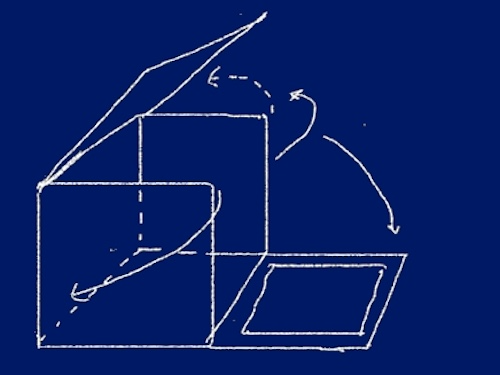
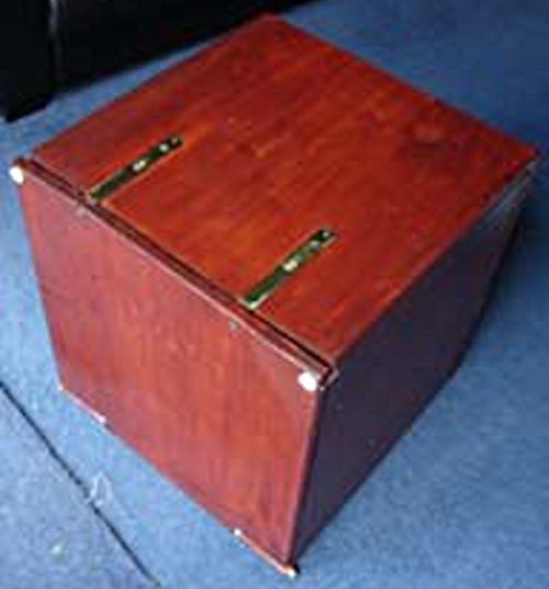
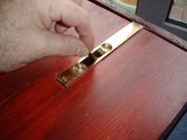
Fig. 1
Pic. 1
Pic. 2
Assembly
The actual ‘strong point’ of the whole assembly is the joint between the back wall ‘B’ and the floor ‘FL’. The joint is made up of a ‘finger joint’ bonded with a strong wood adhesive and backed up with the two brass ‘L’ shaped brackets, and reinforced with a 300mm x 20mm x 20mm length of pine affixed along the length of the joint between the brackets. See fig. 2.
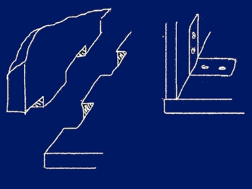
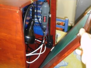
Fig. 2
Pic. 3
Once these two parts were solidly assembled all the ‘moving parts’, S1, S2, T and F could be attached. H = Hinges, T = Top, B = Back, FL = Floor, S1 and S2 = Sides. See fig. 3
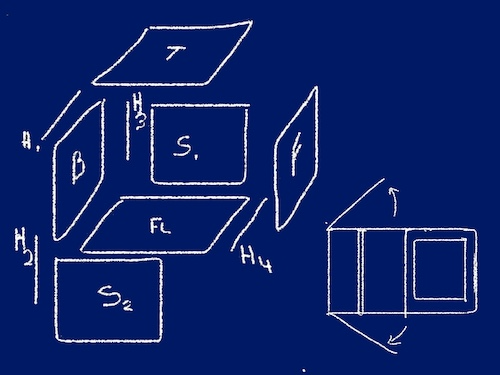
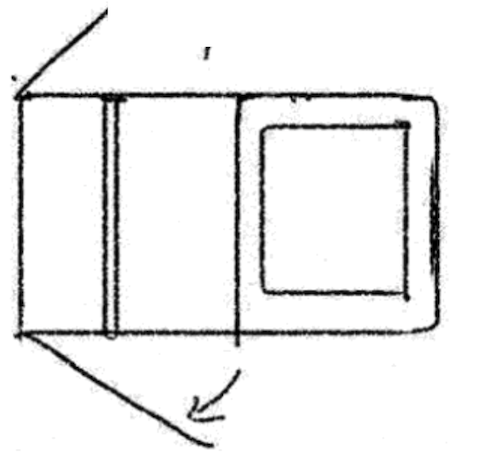
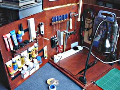
Fig. 3
Top View
Pic. 4
The ten 50mm box hinges fasten the top (T) to the back (B). The sides are then attached and are designed so that one side or the other, or indeed both sides simultaneously can swing out, opening up the work area. The top is attached, and is partly supported by, when in the down position by which ever side is not opened up.
When the top is in the up position, then a strut affixed to the top is then anchored to the back wall. Exactly like the bonnet support on a car.
Two counter sunk bolts lock the front flap/work area in place when the box is closed up. The front of the box is also the extended work area. When the box is closed up it forms the front side of the box. When in the down position it is a work area.
As with any prototype some tweaking was necessary as I decided that I did not trust the piano hinge to connect the front/work surface of the box to the floor of the box. This hinge is to some extent a load bearing point, so it came up with the solution as seen in fig. 4
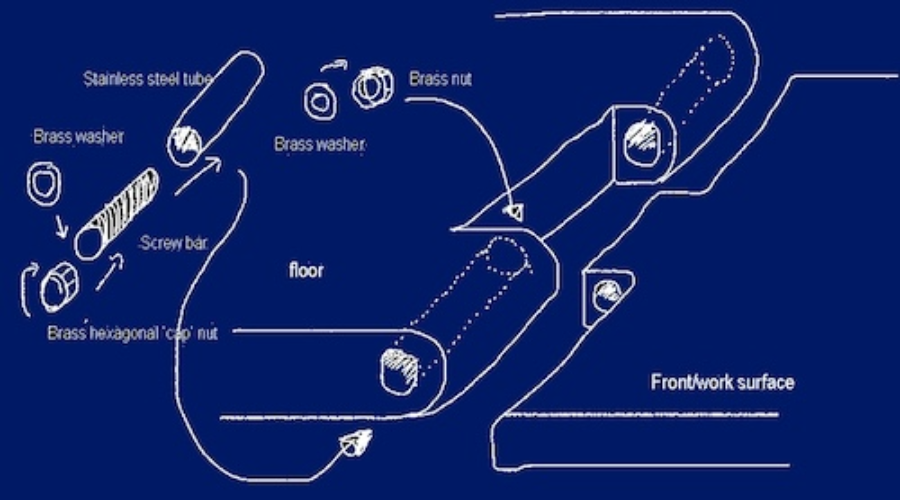
Fig. 4
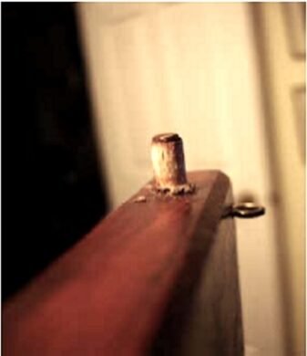
Once all the sides are affixed, I then took measurements for four 5mm dowels that would be sunk into the top edge of each of the side doors. These dowels then engage holes drilled into the bottom side of the lid. These dowels act as a further support for when the WorkShox is closed up. See Pic.5.
Now comes the fun bit, furnishing the interior!
Lighting
The only types of light fitting I could get locally were either the swing arm or bedside table variety, which, on the whole, would not fit, nor could they carry a particularly powerful light bulb.
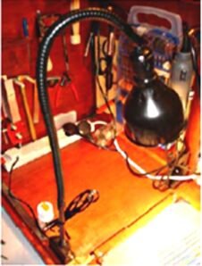
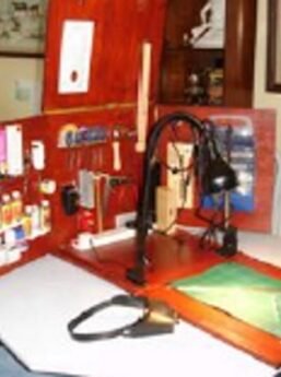
A solution came to hand when I noticed a ‘goose neck’ flexible light fitting in a photograph of an industrial lathe and so I settled on that. The only product of that type that I could get here in Ireland was over €120, however after sniffing around the web, I found a company called Pic.4
VIMCO in New York, that will custom make just such a light to my measurements, wire it put a mount on it and ship it all for a little under €65 and I got it in only two weeks. My thanks go to Dick Fisher for the excellent service and advice (See Pic.9)
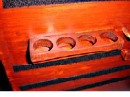
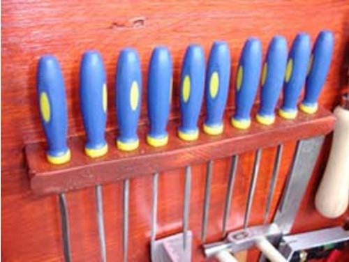
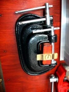
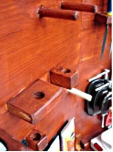
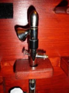
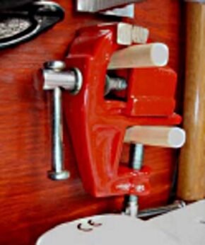
The light now fitted, I fixed the electrical point in place. Fittings where made for the airbrush, files and various tools. 10mm dowels were used to make supports for such items as a vice, hammer and the airbrush etc. Using the same 17mm pine as the outside, I then constructed mounts for the airbrush bottles, needle files, saw and ‘G’ clamps. See pics 6 to 12
Pic. 5
Pic. 6
The whole thing was then disassembled and sanded and stained. There is a myriad of colours from which to choose all of which will highlight the grain beautifully. I decided on marine varnish as a finish. Pic.8
Paints, adhesives and the other fluids were then added. Baring in mind that I had an issue with weight (the box, not my own!), I had to think up a method of storing paints, adhesives, and other fluids. And so the idea of using Velcro strips came to mind. By Placing strips horizontally on the inside of the side, S2., and the corresponding strips cut to appropriate lengths and fixed to the various items that I needed to store, I was able to conveniently and securely store all these items. Lastly a cutting mat was fitted. Pic.9 Pic.10 Pic.11
Pic. 7
Pic. 8
Pic. 9
Pic. 10
Pic. 11
Pic.12
Pic.13
To the outside of the box I placed 8 anti-scratch pads, 4 on the front/ work surface and 4 on the bottom of the box. These are available from most hardware stores
Now I have a suitable work station within the house. It can be set up in a couple of minutes and closed up just a fast.

Of course I now have a storage problem for my creations. And I’ve just discovered 1/6th scale! Where is The Enterprise with it’s ‘holodeck’?
