Scratch Build:
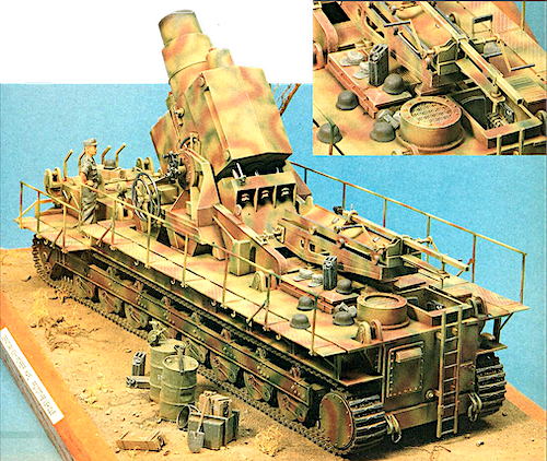
KARL GERÄT
Gerät 040 60cm Mörser Karl
Steve Shrimpton
weighing in at 124 tons and 11.37 metres in length. To move this enormous machine required a 44.5 Daimler-Benz MB503 Vl 2 engine, reaching a maximum speed of l0kph. This limitation made it impractical to travel anywhere other than very short distances under its own power. so the vehicle could be dismantled into several smaller components which could be transported by road on special trailers. Alternatively, the whole vehicle could be slung between two purpose-built railway trucks, suspended above the track by huge cantilever arms.
Seven Karls” were built: there was one prototype and six production vehicles produced by Rheinmetal-Borsig between 1939 and 1941. During 1941 discussions commenced concerning increasing the range of the weapon and in May 1942, 54cm barrels (Gera.L 041) were ordered for the six production vehicles. These smaller calibre barrels where longer than the original 60cm ones. but were completely interchangeable with them, as required.
The 60cm weapon fired the s Be Grenate weighing 2.17 tons and the le Be Grenate weighing 1. 70 tons: the 54cn1 at 1.58 tons and 1.25 tons respectively. The maximum rate of fire was six rounds per hour and the maximum range was 6,675m for the 60cm round and 10,515m for the 54cm round.
In action each Karl was supported by two. fully tracked ammunition carriers which were specially converted PzKpfw IV vehicles, usually Au.sf D or Fl chassis with new superstructures. consisting of an enclosed rack for four rounds over the engine compartment and a crane for ammunition handling fitted to the righthand side of the new superstructure. These vehicles were designated Munitionsschlepper fur Karlgerat.
In construction the Karl was relatively simple. Made entirely of mild steel, the hull was a rectangular box. divided into three compartments. At the front was the engine and driving compartment with the batteries and ancillary equipment at the rear. In between was the gun mount and recoil mechanism.
There were two types of running gear: the prototype differing from the six production vehicles in having eight pairs of road wheels per side instead of eleven. The prototype road wheels were suspended on external swing arms attached to a steel frame running the length of the vehicle. On the production vehicles this mechanism was constructed internally.
The reason for this swing-arm suspension was to enable the hull, which had a steel grid attached to the belly plate. to be lowered lo rest on the ground. thus, spreading the huge recoil forces over a very large area, and relieve excessive stress on the suspension.
In addition, the barrel and the entire gun mount were free to recoil within the hull to absorb as much recoil energy as possible.Loading was carried out by the rounds being placed on the loading tray. immediately behind the breech, by the crane on the Munitionsschlepper. The round was then rammed into the breach by a hand-cranked ram attached to the tray. the round resting on rollers built into the bed of the tray.
To achieve a maximum rate of fire of six rounds per hour Karl was manned by a minimum crew of 22, plus many more in support services – ammunition supply, transport, communications, etc
A brief history of Karl
The official order for Karl was placed in June 1937 and development was directed by General Karl Becker of the Artillery. hence the name Karl was used to describe the vehicle.
A self-propelled chassis was chosen to overcome the limitations of rail- guns. (i.e. large guns constructed on railway carriages) which could only be used where suitable railway tracks were available.
These tracks were also very vulnerable to air attack leading to the destruction or immobilisation of the guns.
By May 1940 the prototype vehicle was ready, and trials were conducted at a test ground at Unterluss. The tests were successful and the/order for the six production vehicles was completed, the delivery of the last gun took place in August 1941.
The guns were numbered I – VI and each was given a name as follows:
I – Adam, II – Eve, Ill – Thor, IV – Odin. V – Loki and VI – Ziu. Guns I – IV were sent to the Russian front in July 1941 with the 628th schwere (heavy) Artillerie Abteilung and saw action at various sites. including Lemberg. in that year.
The best-known action was against Sevastopol in 1942. Later the four guns were issued to the 833rd schwere Arlillerie Abteilung {mot). The last known action was at the siege of Warsaw during the 1944 rising.
It was thought for many years that all the Karl vehicles were destroyed at the end of WWII, despite the fact that US forces captured vehicles II and V in 1945.
However, a recent visit to Russia by staff of the Tank Museum, Bovington, seems to indicate that an example of Karl exists in a military museum near Moscow, together with a working example of the Maus super heavy tank!
The Model
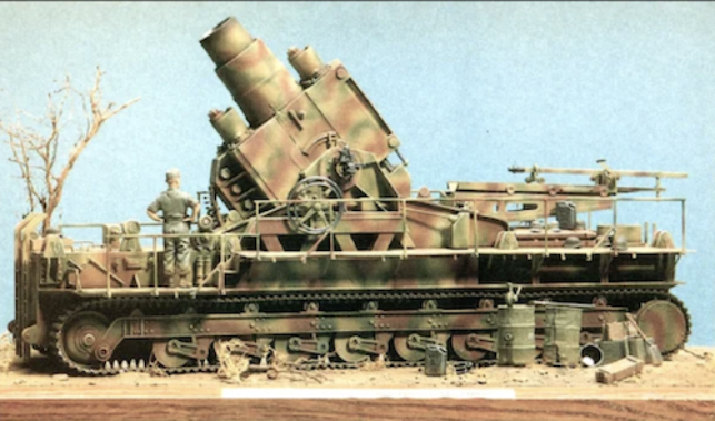
I’ve been modelling “seriously” for about five years and have completed numerous 1:35 scale kits. mainly of WW11 German armour. I started. as we all do, with models built straight from the box. graduating to super-detailing and converting, gaining more experience, and much more pleasure, in the process. Then came the time to progress to the next step – a major scratch build project
l had made one other scratch-built model, a “Dragon Wagon” in l :72 scale, and this gave me the incentive to try something a little bigger.
The choice of subject was not difficult because I had been fascinated by the Karlgeriit ever since I bought a copy of The Encyclopedia of German Tanks of WWII by Chamberlain, Doyle and Jentz, (The “Bible” for German Armour modellers), which contains several pages of useful information and photographs. I had also seen several examples of the kit made by Hasegawa in 1 :72 scale and, all though it is somewhat crude and simplified it gives an impression of the sheer size and “presence” a model in 1:35 scale would have.
I then had to decide between building the prototype and the production vehicles as there are several differences, mainly in the suspension, as I have mentioned previously.
I finally decided on the prototype, having convinced myself that having fewer road wheels it would be simpler to construct! (This conviction grew fainter and fainter as time progressed!)
Several weeks were then spent gathering as much information as I could find, scouring all my books and those of my modelling colleagues until I considered I had enough material to produce some working drawings for the first stage – the construction of the hull.
I was fortunate enough to obtain a set of plans in l :76 scale by J.L. Rue, and some issues of the German magazine, Waffen-Revue which contained a series of articles on Karl including material and photographs from the original design manuals and reports.
The Hull
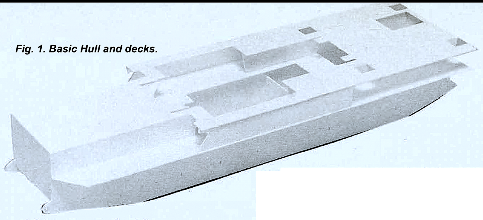
Although it is basically an oblong box, the hull. as it seems. is not quite as straightforward to construct. The belly plate is not flat. but has a section angled up at each end where it meets the end plates. (Fig.1). The supports for the gun cradle are actually wider than the hull and so sections of the side plates have to be removed to accommodate these. The hull was constructed using 40 thou styrene sheet, (or plastic card as it is known to modellers) available, in various thicknesses. from most model and hobby shops.
This is thick enough to give suitable rigidity. a most important consideration in building large structures. In addition I included two extra bulkheads within the hull to ensure that there was no warping or distortion of the hull.
At this stage it should be stressed that great accuracy in measuring, cutting and assembling the various plates is required in order to produce a good 1nodel, and to this end I would recommend the purchase of a good quality steel ruler marked in millimetres (I find it so much easier to work in millimetres than inches) and a small engineer’s steel square as perfect right angles are essential.
Before assembling the hull plates, it is a good idea to mark the position of all the axles required to mount the road wheels and drive wheels. I usually do this by marking the position with a pencil cross and pushing the point of a compass into the very centre to act as a drill guide. After assembling the hull plates with liquid polystyrene glue. check for squareness all round and leave at least overnight to completely set.
The next step is to construct the upper and lower decks which overhang the main hull and act as walkways and track guards as well as the lop of the hull. These I made of 20 thou plastic card to reproduce the scale thickness of the original.
Great care is needed in producing these decks as many apertures have to be cut to allow fixtures such as the lifting brackets and gun mount to be filled. The hull with these decks fitted is shown in Fig.1.
Note the aperture for the driving compartment, and the way the lower deck ”jigsaw” fits inside the hull.
Suspension and running gear
The problem of the running gear had been bothering me for some time. even the prototype required 32 road wheels (and 44 for production vehicles) not to mention the external swing arms and mounting frame. Had I made the wrong choice? A partial solution came by chance on a visit to my local DIY store where I happened to notice some packets of plastic tap washers. which looked remarkably like road wheels and in fact, on closer examination, the 5/8ths inch variety were exactly the right size and thickness, and even had a rim moulded in the right place! All that remained was lo endure the strange looks at the checkout when I paid for 32 plastic tap washers! I didn’t dare try to explain why I wanted them.
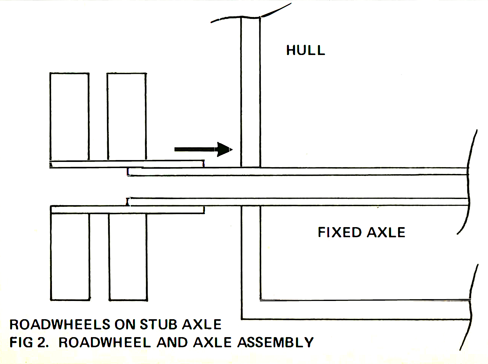
I mounted the pairs of road wheels on stub axles made of aluminium tubing so that they were the correct distance from the hull.’ The stub axles fitted over main axles fixed through the hull at the points previously marked. (Fig. 2). The aluminium tube used is widely available in model and hobby shops in various diameters and has the advantage that it “telescopes”: one size inside the next. Brass and copper lubing is also available. but I find the aluminium easier lo cut. I used super-thin Zap CA “super glue” to secure the road wheels and axles.
The drive sprockets and idler wheels presented similar problems but were again solved when I discovered that the end caps off 35mm film cassettes were exactly right. The drive sprockets consist of two end caps, each with a toothed disc cut from 20 thou plastic card, superglued to the inner faces and spaced with an appropriate length of styrene tube. The outside of the wheel is covered with a plastic card disc detailed with Grandt Line bolt heads. The idler wheels were made in a similar manner only differing in not having the toothed discs and the external detailing is different.
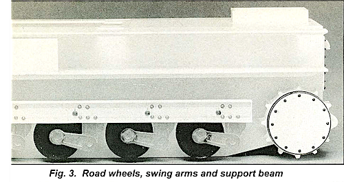
Next the support beams were made from 30 thou plastic card edged with strips of 20 thou, the rivet detail being added by using dome headed brass nails made by Billings and intended for model boat building. First the positions of the rivets are marked and a 0.6mm hole drilled at each mark. The heads of the nails are cut off leaving just enough shank to super glue into each hole. The larger cast rivets were cut from the superstructure of an ltaleri 1 :35 scale Tiger (P) Elefant kit (No.211) and fixed in position with liquid poly.
The return roller fixing points were constructed from plastic card and detailed with a large bolt head from the Verlinden range. For return rollers, I used 1 :72 scale Sherman road wheels mounted in pairs on lengths of brass rod.
The completed beams were installed onto the hull using brackets made from Plastruct “H” -section beam. These are ABS plastic beams of various cross-sections, and sizes intended for architectural modelling and are available from most model shops. They are very useful for converting and scratch building, but as they are not made of styrene, they require the use of their own adhesive. Plasweld, available in small bottles. Plasweld is similar in action to liquid poly and will bond ABS lo ABS or ABS lo styrene. whereas liquid poly will not.
The next step was to produce the 16 swing arms required. eight per side. This could be done by scratch building all 16 (very laborious!) or producing two masters (one for each side. as they are “handed”) and casting off the 16 in resin. I must admit I cheat a little at casting, in as much as I try to make a master with a flat side that can be fixed to a small square of plastic card. This master is then pressed into soft Plasticine and then dusted with talcum powder. With a little practice a good impression can be obtained in this way. The moulds thus obtained, I do several at a time, are placed in the freezer until quite hard, after which casting resin is carefully dropped into the mould from a cocktail stick until it is full. carefully avoiding air bubbles. This system works very well for me and allows me to make many one-piece castings in one go. The swing arm castings were then super-glued to the road wheels and support beam. (Fig. 3).
To complete the running gear, suitable tracks had to be found. On closer examination of various photographs of the vehicle, I noticed that the tracks of the prototype were not the same as the production vehicles; the track links being much narrower in pitch. They were very similar to Tiger (PJ Elefant tracks, which was a great relief to me as I had some to hand and did not like the idea of scratch building such long lengths of track required. The Elefant tracks are, however. some 2mm too wide. but after this is removed 1mm from each edge. two sets being required to provide enough track for such a large model. they fill perfectly.
Detailing the hull
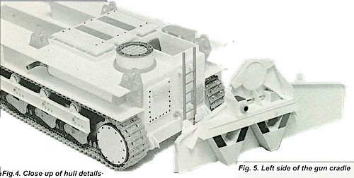
At this stage I decided to add the remaining major components on the hull. These include the driving compartment, engine louvres. cooling fan duct, exhausts. access panels. lifting brackets. etc. (Fig. 4). Most of these were build using sheet and strip styrene. detailed with Grandt Line nuts and bolts and many parts from the spares box. Points of interest to note are the grilles on the intake louvres, the n1esh on the cooling fan duct and the lifting brackets. The grilles are made of etched brass and is one of a large selection of etched brass sheets made by Scale Link, this one being a square grid with holes approximately 1 mm square. Its reference nun1ber in the Scale Link range is 4mm F60. Fine nylon mesh is used for the cooling fan duct outlet, this being “Mesh Wire”‘ from the Verlinden range. It has a fine diamond pattern and is ideal for scale wire mesh applications.
The eight lifting brackets are, like the swing arms, cast using my Plasticine method, but due to their more complex shape have to be cast in two sections which are then super-glued together. The lifting bracket pins are Verlinden turned brass shell cases cut to length detailed with etched brass retaining chains from the P.P. Aeroparts 1:72 Accessories set GA714. I’ve found many useful items in accessory ranges designed for railway and aircraft modellers.
Another item cast in resin were the end caps of the exhaust silencers, located between the decks on either side of the engine compartment. These were made using the dished head of a drawing pin as the master and proved to be the size and shape required. They were then super-glued to the ends of a suitable length of styrene tube and an exhaust pipe added to one end. The pipe itself was made from a curved comer section of kit sprue cut to size and the end drilled out to represent the hollow tube. Only the prototype vehicle had these short, right-angled exhaust pipes. the production models had extended exhaust pipes running almost the entire length of the vehicle.
One item I missed at this stage was an access hatch in the rear deck. None of my photographic references showed this area well and it wasn’t until the model was almost complete, that I noticed the hatch on a small line drawing in one of the Waffen Revue magazine articles. It is located on the rear deck between the two pairs of grab handles near the access ladders. I made it from 10 thou plastic card, the shape being rectangular with small radiused corners, and detailed it with Grandt Line hinges and bolt heads and a brass wire handle.
Gun Cradle
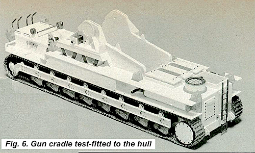
I found the gun cradle a fairly complex sub-assembly to construct, due mainly to the angular nature of the various plates and supports. However, by building the two sides simultaneously (they are mirror images, apart from the laying and sighting mechanism on the left side), matching each piece as I slowly assembled the cradle, I found that frustrations could be kept at a minimum.
The main side plates are of 40 thou plastic card and the supports and braces made using 10 to 40 thou thicknesses to match the scale thickness of the original. The V-shaped box girders were made using Plastruct ”I” – section bea1ns as a base boxed in with 10 thou plastic card (Fig. 5).
At this stage the centre of the gun trunnions on the mount should be marked and drilled to accept the brass tube spigots that will be built into the body of the gun to allow il to elevate. Accuracy here is vital as the gun must fit into the cradle square and true. The two halves of the cradle can now be joined by bulkheads of 40 thou plastic card. so that the whole assembly fits accurately into the recess cut in the top deck of the hull. as in Fig. 6.
The rivet detail was lhen added to the cradle using an etched-brass sheet produced by Scale Link. This sheet consists of a fret of brass strips of various widths, half of which have rivet heads etched onto them.
The thin strips have a single row of rivet heads and the wide ones have two rows of heads.
The strips are very thin, about 5thou and can easily be cut and bent to conform to various shapes and curves. The reference number for this etched sheet is Fl6 and it’s one of many produced by Scale Link, many of which are very useful to military modellers.
Other details were added to the cradle at this point, such as Grandt Line bolt heads and lifting rings. The basic components for the gun elevating mechanism were also added to the left side of the cradle just below the trunnion. the final detailing was added later.
Gun and recoil mechanism
My main problem at this stage was to find a tube of suitable diameter to form he basic barrel from breech block to the rear of the barrel shroud. I finally found the ideal tube, which was, in fact. a piece of plastic conduit used by electricians. having an exterior diameter of 20mm and an interior diameter of 16.5mm which scales out to approximately the correct size for 1 :35 scale.
The tapered muzzle end of the barrel seemed to be another problem. until I realised that the spout on the lid of a Patterson film processing tank was the exact shape and size; and I had an old unused one at hand! (These tanks are also made of a styrene type plastic which can be bonded using liquid poly).
The complete barrel was made up using a suitable length of conduit tube to which was added the processing tank spout.
The recoil section was constructed next. This consists of a rectangular box with a slightly pitched “roof·.
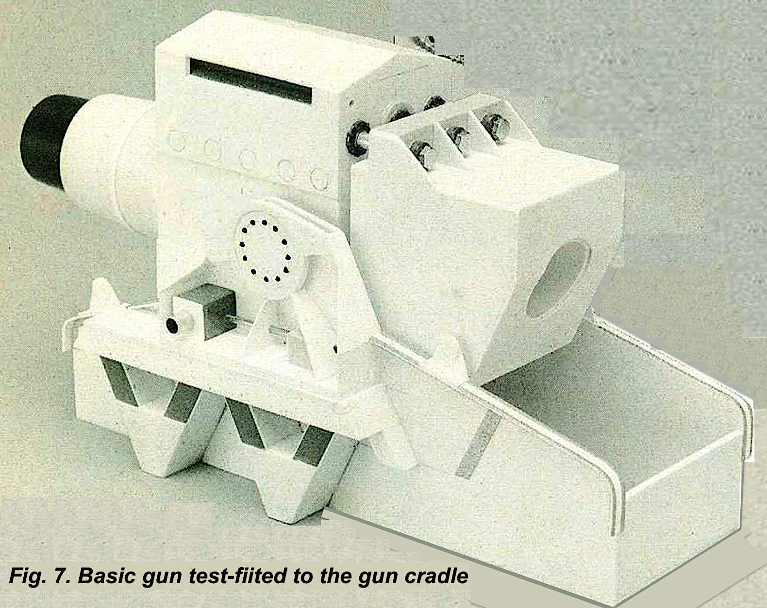
In reality this section was made up of three separate parts bolted together. The top and bottom containing the recoil cylinders. three in each, and the centre supporting the barrel. The top and bottom sections were slightly wider than the centre and this was represented by adding 20 thou styrene sheet to each side (Fig. 7).
The six recoil piston rods were to be made of 1/8th of an inch aluminium tube and so holes of a suitable diameter were made in the rear face of the recoil sections to accept these and detailed with circular plates from the ltaleri Elefant kit.
Next, the massive breechblock was made from 30 thou plastic card. It initially looks complex but is basically a slightly misshapen cube with extensions top and bottom to take the ends of the recoil piston rods.
The extensions were made from square section Plastruct tube and fillets of 30 thou plastic card (Fig. 7). Holes were drilled in the appropriate places to accept the recoil piston rods which were super-glued in place.
The huge hexagonal bolt heads which secured these rods on the original were represented by brass bolts, precision made for n1odel engineering and, together with matching washers and nuts, are available from many· hobby and model shops. These were super glued into the outer ends of the rods with the inclusion of 1/8th inch styrene spacers (Fig. 7).
These bolt heads, together with those on the elevating mechanism below the gun. are one of the characteristic features of the Karl to my mind.
These three components, barrel, recoil block and breech block, were then assembled to form the basic gun, to which the barrel shroud was added to the front of the recoil block. Finally, when all joints were cured, aluminium tube spigots were super glued into holes in the recoil block so that the gun could be fitted to the gun cradle, using spacers to ensure that it sits centrally in the cradle and is capable of elevating smoothly (Fig. 7).
When I was happy with the fit of the basic gun in the cradle, I removed it and added the other details to complete the assembly. The front ends of the recoil cylinders were added, the central one being larger than the outer two. These two larger cylinders were made of brass tube and styrene sheet detailed with brass nuts and smaller Verlinden nuts. set on styrene plates above and below the barrel. Nuts for the outer cylinders were added lo the plates on either side of the central cylinders (Fig. 8).
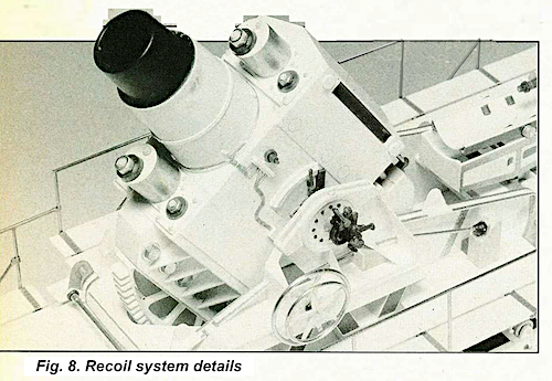
Below the gun was added the elevating mechanism consisting of a radiused gear rack set on a square beam detailed with styrene fillets and brass nuts, bolts and washers. (Fig. 8).
The square beam was again made using Plastruct square section tube of the correct size with the ends blanked off with 10 thou plastic card. This was secured centrally to the base plate of the recoil section and onto this was cemented the elevating gear rack so completing this assembly.
Loading tray
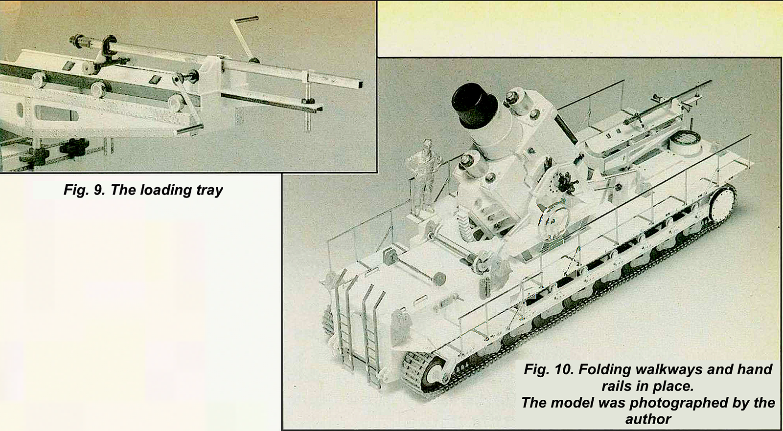
The main frame was constructed of 30 thou plastic card and detailed with Scale Link rivet strips of various sizes as necessary and two support legs of aluminium tube were super glued to an internal bulkhead to enable it to be attached to the rear of the gun cradle. (Fig. 9).
The curved upper tray was heat formed around a suitable diameter former by taping a piece of 20 thou plastic card to the farmer and dipping it into boiling water, having previously cut the six square holes to accept the rollers that will be inserted later. Plastruct angle strips were cemented to each side together with the six small wheels that enabled the tray on the real vehicle to move back and forth so that the round was maneuvered as close to the breech as possible.
These wheels were made using the white metal inserts contained in the aircraft tie-down set mentioned earlier.
The crank mechanism and housing were next made and added to the rear of the loading tray, the handles being made of brass rod and strip detailed with Grandt Line nuts.
The ramrod was made of square section brass rod with various parts roller from the section spares (Fig. box 9).
The make gun and the loading tray were then fitted to the gun cradle and the whole assembly was test fitted into the hull to ensure all was well.
The folding walkways
The final major components to make were the folding walkways which run the entire length of the vehicle split onto two levels just forwards of the gun cradle.
These were made of 20 thou plastic card detailed with rivet strips where the hinge supports are located, and in between these are sections of textured 10 thou plastic card made to represent non-slip steel plate. The walkways were connected to the decks by supports made from “U” -section Plastruct strips located below the rivet strips.
A small gap of approximately 2mm was left between decks and walkways as on the real vehicle: these were folded up for transport to reduce the width of the vehicle. (Fig. 10).
Lastly the rails were made using brass rod soldered together to provide sufficient strength and rigidity. Accurate alignment was ensured by taping the pre-cut pieces of brass to a sheet of graph paper in turn taped to a Oat board. Each joint was then carefully soldered using fine solder wire and a pointed soldering iron.
When cool the joints were filed to remove excess solder and the rails were super glued to the walkways, the hinges detailed with brass strip and Grandt Line nuts.
To complete the model final detailing was carried out adding such items as the elevating wheels, sighting equipment. towing shackles, tools and stowage boxes, etc., using various photographs of Karl in action as reference.
Painting
Although the model represents the early prototype vehicle, there is some evidence, including photographs, which suggest that this vehicle was used in action. probably to replace gun number IV Odin which had been damaged by enemy action while serving on the Eastern front in 1943 or 1944.
Therefore, I decided on the late war colour scheme of Dark Yellow with camouflage markings of Olive Green and Red-Brown. But this posed a problem, because at this time Humbrol had their disastrous fire at Marfleet causing a subsequent reduction of their paint range; my favourite colour for representing Dark Yellow was no longer available.
This colour was Humbrol’s WW1 German Pale Yellow which, to my eye, gave the truest colour match available. In the end I chose to use Tamiya Acrylic Dark Yellow as the base coat and Humbrol German Camouflage Green and Red Brown for the random camouflage pattern. all applied with a De Vilbiss Super 63 airbrush.
The tracks were sprayed with a mixture of Dark Earth and Black and when dry they were dry brushed with Dark Earth then a lighter Dark Earth mix and finally silver on the guide teeth and edges of the track shoes.
The whole model was dry brushed with light Dark Yellow mix to pull out all the raised detail. I really enjoy this process. as I feel it really brings a model to life and gives it character if done with care and subtlety.
Weathering was carried out using pastel chalks. powdered. and applied with a fine brush around au raised detail and in angles and recesses. Black was mainly used. with touches of dark brown, on the upper hull and earth colour around the lower hull.
This was kept to a minimum as I wanted the model to appear as a recently upgraded vehicle just arrived in its firing position on the Eastern Front.
The base
The base was made from a suitable piece of oak, the edges varnished and masked with tape when dry. A mixture of ready mixed Polyfilla and white glue was spread over the base into a thin, slightly undulating layer. Diluted white glue (PVA) was brushed over this and my “texturing mix” was sprinkled on. This mix consists of old mortar and brick dust collected from demolition sites which I find gives a perfect mix of particle size and texture for ground work.
When dry the tape was removed from the edges and the excess “texturing mix” was shaken off. The groundwork sprayed with a Dark Earth/Black mixture. Dry brushing was carried out using various Dark Earth/White mixtures.
Finally, Karl was fixed in place, using white glue, together with various crates, barrels, jerricans, etc. The tree, in fact a piece of real tree root. was glued into a hole drilled into the base and pieces of lichen secured with white glue finished the groundwork.
Although the model was now complete, I felt
that something was lacking, so I decided to add a figure to the model, partly to add human interest. but mainly to give an impression of scale and put the size of the vehicle into perspective. I am, however. no great figure painter, but I did my best and hope that the desired effect has been achieved.
The model took some seven months to lan and construct and, although frustrating at times. I learned a great deal and found the project most enjoyable.
When the model was finished l vowed, I would never take on such a complex scratch build again, but recently I came across a set of drawings for the 80cm Schwere Gustav. or Dora rail gun and I felt the old urge again.
Well, maybe next year!
Finally, I would like to thank the members of my local modelling club, especially Chris Pearce, for their encouragement and help in supplying books and reference material without which this model would never have been completed.♦
Sources
Plastruct Shapes and Plasweld Solvent: EMA Model Supplies Ltd., Feltham. Middlesex.
Brass and Aluminium Shapes: K & S Engineering Co., Chicago.
Verlinden Productions and Grandt Line Products: Historex Agents, 3 Castle Street, Dover, Kenl CT16 lQJ.
Scale Link: 1 78 High Street. Teddington, Middlesex 1Wl 1 8HU.
