Geoffrey Futter
presents:
The Sherman Crab Mine Clearing tank.
Top.
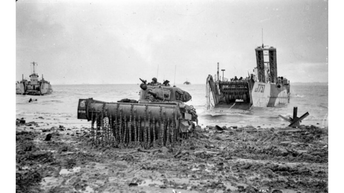
a Sherman Crab Mark I drives ashore during the assault on the island of Walcheren. Another Crab can be seen emerging from LCT 737 while a S.B.G. bridge waits in the hold of the LCT. (I.W.M. photograph).
TWO TYPES OF MINE CLEARING
vehicles were used operationally by the 79th Armoured Division, these being the Churchill fitted with the Bullshorn plough and the Sherman Crab. The first type, which will be described in a later article in this series, was used in small numbers by the division on the Normandy beaches on D-Day but the Sherman Crab, which is dealt with this month, gave useful service on the Normandy beaches and was also extensively used throughout the N.W. Europe campaign in considerable numbers.
Three Regiments of the division (the 22nd Dragoons. the 1 st Lothian and Border Yeomanry and the Westminster Dragoons) were equipped with Sherman Crabs and these came under the direct command of 30th Armoured Brigade. Other mine clearing devices were used by the division but these, such as the Conger and Snake, only required vehicles to tow or push them. or to act as carriers for them, and were not integral parts of vehicles. Some of these devices will be described and illustrated towards the end of this series of articles along with other miscellaneous types used by the 79th Armoured Division. The Sherman Crab was a Sherman V (M4A4) gun tank fitted with the rotating flail device which had been so successfully used in the Middle East in the form of the Scorpion mine exploding vehicles based on the Matilda. Grant, Valentine and described and drawn by Geoffrey W. Futter Sherma11 tanks.
The flail device consisted of a revolving drum fitted on arms at the front of the tank and chains which were attached to the drum beat the ground as the drum revolved to explode any buried mines which were in the path of the tank. The Middle East types mentioned above were fitted with auxiliary engines to drive the chain drum but the drum on the Sherman Crab was driven by means of chains coupled to the main drive shaft of the tank via a transmission shaft fitted along the top of the right hand arm. The normal turret armament was retained so when the Sherman Crab was not engaged in flailing it could be used as a gun tank. Because of the late arrival of D.D. Shermans on the Normandy beaches on D-Day this became a major role for the Sherman Crabs which had landed from beached landing craft.
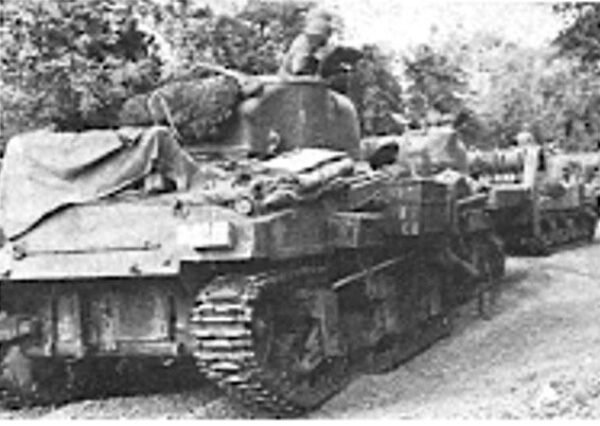

Top Left, Sherman Crabs of the 7th Armoured Division wait to cross the River Orne in July 1944. The nearest Crab has the chain drum arms in the lowered position so that the chains are dragging along the ground but the others have the arms in the raised position to keep the chain clear of the ground to reduce chain wear. (I.W.M. photograph)
Top Right, At right, rear view of a Sherman Crab Mark II, showing clearly the station keeping lights and the chalk containers. Compare the design of the chain drum arm with that of the Mark I. (R A.C. Tank Museum photograph)
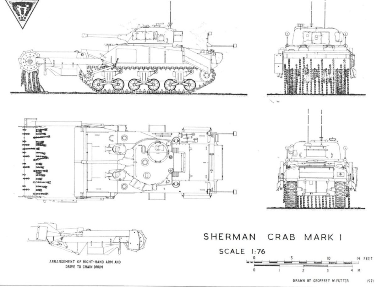
The Sherman Crab was developed initially into the Mark I version of this type, which served with the division throughout the N.W. Europe campaign, was provided with hydraulic jacks which could raise the flail arms to er.able the hanging chains to be clear of the ground when the Crab was not flailing, although this was not always done as mar.y photographs depict them on the move with the chains dragging along the ground.
The Mark II version, which was not produced in sufficient numbers in time for it to be used by the division, had modifications incorporated in the flail arms which enabled the chain drum to remain at a constant height above the ground at all times when flailing to avoid mines which had been placed in depressions being missed by the beating chains as could occur with the Mark I version. Heavy chain wear occurred when flailing was carried out on roads and other hard surfaces and the chains also became distorted from the blast of exploding mines. The division fitted brackets to the hu II sides of most Crabs for the stowage of spare chains and when a Crab was disabled the chains were usually removed, if circumstances allowed, to enable an adequate supply of spares to be always available. Flailing was generally effective at shallow depth but deeper laid mines could be missed and then detonate later after many vehicles had passed over them.
Other features of the standard production Mark I version were w,re cuttus at each end of the chain drum, an armoured shield fitted over the nose of the hull between the arms to protect the Sherman from blast, and steel plate shields were carried on brackets under each arm. As with most of the other specialised armoured vehicles of the division modifications were incorporated by the division as the campaign progressed to improve the operational efficiency of the Crab in circumstances which were not foreseen when the vehicle type was produced in the factory. The Crabs used on D-Day were standard production vehicles but during the subsequent campaign they became much more sophisticated vehicles as the various modifications, some of which are briefly described here, were carried out. Special cowls (shown on the scale drawings) were devised and fitted over the hull and turret periscopes to improve visibility when flailing was undertaken over dry ground, when a considerable amount of dust would be thrown up, and the mantlet and turret ring were sealed to stop the entry of dust.
A Crab regiment was organised as a normal armoured regiment with Regimental Headquarters and three fighting squadrons. Each squadron consisted of three troops with five Crabs in each troop. To clear a lane through a minefield three Crabs of a troop flailed in echelon formation and with proper formation keeping could clear a lane 24 feet wide. The remaining two Crabs of the troop would usually stand by as reserves and to give any covering fire that might be required. To assist the Crab driver.; to move forward in the correct formation and at the required distance from one vehicle to another special station keeping lights were devised and eventually fitted to all Crabs. These took the form of rearward shining lights on tubular arms fitted on the rear corners of the tank hull and when not in use they could be folded down on the hull and retained in special brackets. The scale drawings depict the lights in the raised position and also showed them fitted with cowls which were added late in the campaign. Lane marking devices were also fitted and these were of two types. Firstly containers of powdered chalk were carried on the sides of the hull as shown on the scale drawings and to mark the edge of the swept lane chalk trickled out as the Crab moved forward through the lane.
Later these were superseded by flagged markers (‘Whyman’ markers) which were fired into the ground at regular intervals from special frames fitted on the hull sides as the lane was cleared. These markers could also be fitted with dimly shining lights for use in conditions of bad visibility. The Sherman Crab proved to be the most efficient and practicable method of clearing anti-tank mines during the N.W. Europe campaign. Most of the flailing that was required was in the advance through France where it had been estimated that the German troops had laid 100,000,000 mines; few in comparison had been laid in Germany itself.
MODELLING THE SHERMAN CRAB
to 1 /76th Scale
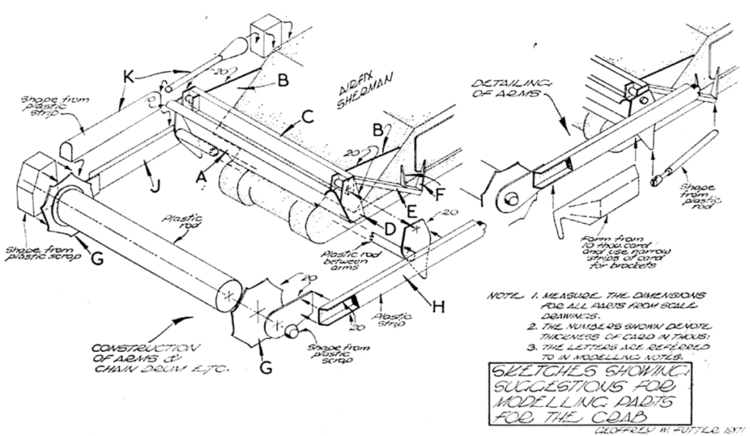
For this month’s conversion project the Airfix Sherman kit is required and, as the first stage of modelling the Crab, assemble this kit precisely as described in the Airfix instructions. While working on the remainder of the project reference should be made to the scale drawings and sketches. The sizes and shape of all the parts required for modelling should be copied from the scale drawings.
The armour protection to the front of the hull should now be added to the Airfix Sherman and the sketches show the arrangement of this. Thin plastic card can be used for the armour with the top of the frontal armour plate (shown at A on the sketches) carefully bent to represent the roll-over at the top. In conjunction with this stage of modelling a strip of plastic should be cemented in place where shown across the side armour plates (B) as the steel channel (C) which was one of the main structural members of the support for the chain drum arms on the full size Crab.
On the ends of this strip cement cut-out pieces of card for the plates (D) on which the chain drum arms pivotted at the same time cementing into place strips of plastic to represent the steel members (E) to which the rear ends of the hydraulic jacks were fitted. Small tapered pieces of card can be cemented in place on the hull sides as the strengthening brackets ( F). Next prepare the chain drum from plastic rod and , cut the toothed end plates ( G) and the plain inner plates from plastic card, then cement these together making sure that the drum is centred correctly on the end plates before the cement has set.
The arms (H & J) can now be prepared as shown on the sketches and then joined to the chain drum and to the already adapted Sherman. If the modeller wishes he could pin the arms to the drum and at the pivot point on the structure added to the front of the Sherman to enable them to move but at such a reduced scale this is not really necessary.
By reference to the sketches model the parts for the transmission (K) for fitting to the right har.d arm and then add these to the model. All that remains to complete the front part of the Crab model is to add the chair.s to the drum and this will be the most difficult part of the project and a certain amount of patience will be required if the riqht effect is to be achieved.
Most good modelling shops will be able to supply lengths of fine chain suitable for the purpose and the best way to fit the chain to the drum will be to make a small hole with the point of a heated pin in the roller at each point where a chain is to be fitted and then cement a short length of fuse wire, which has been looped in the end link of the chain, into the hole.
The end result will look right if the chain fixing points are set out correctly around the drum but it will not produce a model which can receive a lot of handling without damage. If the modeller can find a length of plastic tube of the correct scale diameter, instead of using plastic rod, it may be easier to fit the chains to this by the means described.

Top.
Brig. N. W. Duncan (now MajGen. N. W. Duncan the author of some of the recent A.F.V. Profile series of booklets), the Commander of 30th Armoured Brigade sits on a bank to watch the Crabs of his Brigade in action on the approaches to Caen. (I.W.M. Photograph.)
To complete the model the periscope cowls can be shaped from plastic scrap and then cemented in position and the stowage bins normally carried on the rear of the hull and turret can be shaped from plastic strip or built up from plastic card. The station keer,,ir,g lights can be made from small diameter plastic rod with plastic card discs cemented on the ends of the rod as the light shields. The chalk containers can be cut from stout card and then fitted on the hull sides with spacing pieces of plastic strip cemented between the containers and the hull to keep the containers at the correct scale distance from the hull sides.
After carrying out any filling and sanding that may be require the model can be painted overall with Humbrol dark earth matt enamel. The 79th Armoured Division emblem was normally stencilled on the rear of the hull at the left hand side and also on the front of the drive housing on the right hand end of the chain drum.

