SWEDEN’S
ARMY SNOW VEHICLES ■■■■
The Volvo (Bolinder-Munktell) BV 202 SNOWCAT
by Geoffrey W. Futter
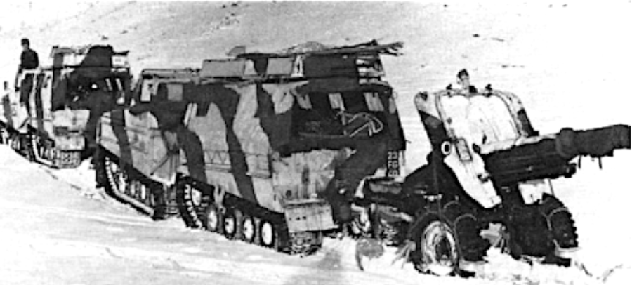
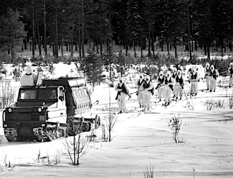
In the heading photo, a BV202 G.S. version tows a 105 mm. pack-howitzer during exercises in Norway.The Pack Howitzer is camouflaged in the same manner as the DV202 and it can be c:early seen how the skis are chained to the wheels of the gun. Official army photograph.
During the years 1954-1956 the Swedish Army Ordnance Department obtained various snow vehicles for testing and evaluation, but none of these apparently met the demands of the Swedish Army and as a result some Swedish motor manufacturing concerns, including BolinderMunktell {a company of the Volvo Group), were invited to design and manufacture a vehicle to replace the Weasel.
As none of these industrial concerns was interested in this work, the Army Ordnance department themselves carried out the necessary research into what form the replacement vehicle should take and during this re search it was decided that an articulated steering tracked vehicle was the most acceptable for the duties expected of the vehicle and in 1957 decided to design such a vehicle themselves.
During these trials it was found that the articulated steering type of tracked vehicle was so superior to any other form of vehicle that the major Swedish motor manufacturing firms were provided with the design in 1961 and invited to submit competitive tenders for its manufacture.
The Volvo Group was successful in this tender, receiving both an order for production of the vehicle-s. and also a contract for further development of the vehicle type. Bolinder-Munktell of Eskilstuna, a wholly owned subsidiary of the Volvo Group, were dele{Jated the entire work on behalf of the Group. behalf of the Group.
Primarily, the BV 202, as this vehicle type is designated, is designed to transport materials and personnel off the road over deep, loose snow, but can also operate over marshes and hard ground, and it can also swim.
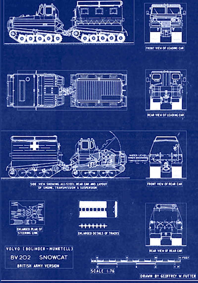
Since the vehicle is made of two units the track area is large, with the resulting ground pressure low and the steering resistance minimal. The ground pressure is, in fact, only slightly in excess of that of a man on skis.
The front car contains the engine, gearboxes, steering assembly and the driver’s cab, which is heated and insulated from the noise of the engine and transmissions and can accommodate one passenger in addition to the driver.
The rear car is shaped to provide seating space for 8-10 passengers but can also be used to carry general cargo instead of personnel. The roof rack can carry field equipment, skis, etc. Both cars are fitted with sturdy steel tube bumpers. Access into the cab is gained by the side windows and roof hatches hinging upwards from the centre line of the vehicle.
Power is supplied by a Volvo B.18 four cylinder petrol engine with the drive by propeller shafts to the drive axles of the front and rear cars.
The propeller shaft to the rear car passes through the steering link. Each track consists of two thick rubber belts on to which are moulded the straight rubber grousers (full track width and shorter width alternately) and the tracks are provided internally with light alloy guide lugs.
The vehicle is supported on the tracks by pneumatic rubber tired wheels with torsion bar suspension and the upper track is carried on small diameter twin wheels. The drive wheels are provided with rubber sprocket teeth which engage in the track cross bars between the rubber belts. The rear wheel of each track unit is used for tensioning the tracks and is provided with its own rubber spring suspension and threaded tensioning rod. This tensioning rod incorporates a shear device which breaks if the track should be tensioned too hard.
The remaining four suspension wheels each side are carried in pairs by bogie arms on torsion bars. As the front pair of wheels are more heavily loaded when traversing uneven ground the movement of these pairs is dampened by rubber buffer springs. The track car is braked by a drum brake with internally expanding brake shoes. The brake is fitted on the rear output shaft of the distribution gearbox and is hydraulically controlled by the brake pedal and mechanically by the hand brake lever.
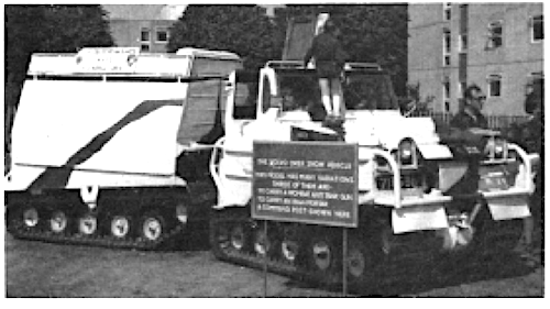
Each of the cars can tilt vertically up or down in relation to each other, with an angle of 35° being allowed by the design of the link. This movement is dampened and stopped by rubber springs which for protection are enclosed in rubber bellows. The two joints in the link which allow vertical movement enable the two cars to run at different levels up to a maximum of seven inches. The two cars can also tilt up to a maximum of 35° in relation to each other about the longitudinal axis.
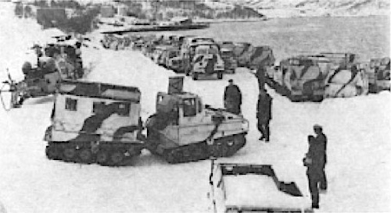
This photograph shows the British Army vehicles assembled in Norway in readi. ness to undertake Arctic warfare train• ing. The majority of the vehicles are G.S. versions of the BV202 but others that can be seen are Landrovers and Bedford G.S. trucks. On the extreme left of the picture is a Sioux helicopter with rotor blades removed and fitted with skis.
An official Army photograph.
A large number of these vehicles have been in service with the Swedish and Norwegian Armies for some time and the BV 202 is now in service with the British Army.
The main role in which these are used by the British Army is for the transporting of personnel and equipment over snow, and this G.S. version has the rear car covered by a canvas tilt with translucent panels.
Ambulance and Command Post versions are also in service and these have the rear car to• tally enclosed by a sheet steel super-structure with the Command Post version fitted with wireless aerials on both the front and rear cars.
The BV 202 is also used to transport the 81 mm mortar and Wombat anti-tank gun and in addition the G.S. version also serves as a towing vehicle for the 105 mm pack-howitzer which is fitted with skis when being towed over snow.
The vehicles that undertook trials with the British Army, before the type was accepted for service, were finished olive green overall and carried standard British Army number plates, an example being 20 BT 93.
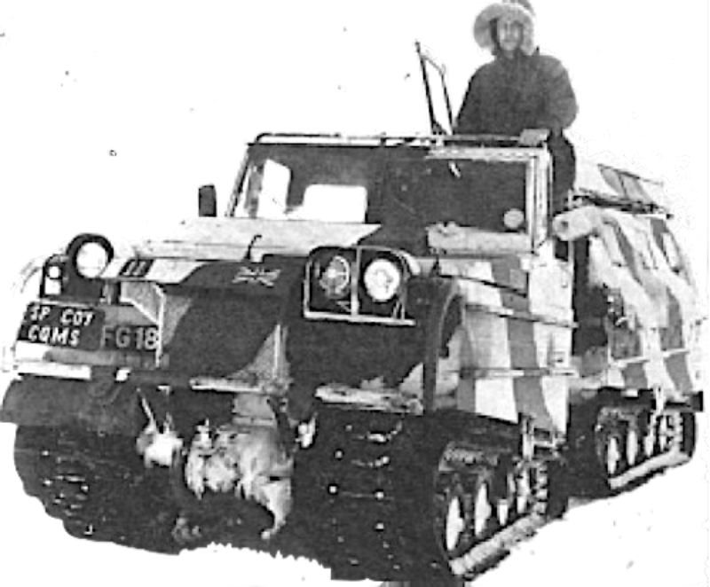
An interesting front view of the BV202 G.S. version which clearly shows the front towing eyes and the rubber tracks. All these vehicles have left-hand drive and, in this photograph, the driver has raised the cab side windows and roof hatch which hinge upwards on the centre line of the vehicle.
An official Army photograph.
Those now in regular service are still finished in this basic overall colour but are overpainted with random patches of white paint which on most of the vehicles seen has been very crudely applied.
Small reproductions of the Union Jack are painted on the front and rear of the vehicles and standard white on black number plates are carried. Examples of these number plates are 71 BG 86 and 71 BG 87 on Command Post versions, and 22 FG 97, 23 FG 16 to 18, 23 FG 29, 23 FG 30 and 23 FG 40 on G.S. versions.
These British BV 202 vehicles are used by elements of the Strategic Command to gain experience in arctic warfare conditions during exercises which normally take place in Norway in conjunction with other N.A.T.O. Armies.)
SCRATCH-BUILDING:
THE BRITISH ARMY BV 202 SNOWCAT
To: 1/76th SCALE-modelling details
By Geoffrey W. Futter
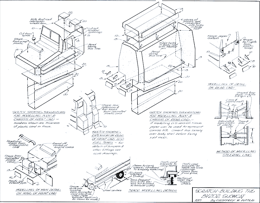
The only major problem the modeller might encounter is to find a source of supply for the 20 wheels which are required, although how to model these oneself is dealt with in the following modelling notes. These notes which describe the modelling of the BV202 stage by stage, should be read in conjunction with the accompanying sketches and scale drawings.
A few liberties have been taken in the suggestions for modelling certain component parts to simplify construction owing to the small scale but these, which are connected with the suspension and track assemblies and also the steering link, will not distract from the finished model having an authentic appearance when completed. This has to be done now and again when scratch-building the smaller vehicle types to such a reduced scale but of course should be restricted, where possible, to hidden or mainly obscured components or assemblies.
Stage One
From plastic card of the thicknesses suggested on the sketches cut out the various pieces required to form the chassis and bodies of the two cars.
The outline shape of each part must be carefully traced or measured from the scale drawings and then transferred on to the plastic card with an allowance being made where necessary for the thickness of the card at the overlaps at the joints.
After checking that the size and fit of all the parts is satisfactory cement together and when the joints are set, sand as necessary to ensure a smooth finish overall and to provide rounded corners to the top of the engine cover of the front car.
This sanding should not be neglected at this stage as it will be virtually impossible to carry this out satisfactorily after the smaller details have been added.
Stage Two
The sketches show how the main details can be modelled for adding to the bodies of the two cars and further instructions regarding these should not be necessary. The smaller details such as the tubular bumpers, headlamps, fire extinguishers etc. have been omitted from the sketches for clarity and as it will be easier to model these by reference to the scale drawings.
Slaters microrod should be used for the tubular bumpers carefully bending the lengths required to the correct curvature by laying the plastic rod over the particular bumpers being modelled on the scale drawings. To be sure that the bumper assemblies will be as rigid as possible after completion and fixing to the model, the lengths of rod which join directly to the car bodies should preferably be cemented in to holes (formed with a hot pin) in the body shells and not just cemented end-on to the bodies.
The fire extinguishers on the rear of the front car, the fuel tank filler caps and the headlamps can be provided from plastic rod or sprue of suitable diameter, cut to required length and then cemented in place.
The brackets on the roof of the front car and which support the roof hatches when open can be made from thin gauge plastic card and the jack which is stowed on the front of the rear car can be built up from pieces of plastic card or shaped from plastic scrap.
If the modeller has two jerrycans left over from previous 1 /76 scale modelling projects these can be cemented directly on to the front of the rear car in the positions shown or if such jerrycans are not available they can be cut from laminated card. The retaining straps can be represented by narrow strips of paper.
If the G.S. version is being modelled the tilt can, as mentioned on the sketches, be represented by using tissue paper which should be cemented over the body shell before the roof rack is fixed in position but whichever version is being modelled a tissue paper curtain is required over what would be the access opening in the rear car.
The spade which is normally carried on the rear of the roof rack can be cut from thin plastic card and then cemented in position and the towing hawser which is stowed around the roof rack brackets can be of fuse wire or thread, painted black, but should not be fixed on the car until the paint finish has been applied.
Stage Three
The arrangement of the steering link which, on the full size vehicle is complex, must be simplified for modelling to 1 /76 scale and how this can be done is shown on the sketches.
If this is followed the general appearance of the modelled steering link should not differ noticeably from that of the full size link.
Stage Four
Before considering the modelling of the track assemblies the modeller should prepare the necessary number of 5 mm. diameter wheels which are required if these are not available to him ready made.
These wheels can be made in the following manner from laminated card. Each wheel will be comprised of 3 discs each of 20 thou. thickness card and of 5 mm. diameter which will be cemented together to give the required thickness for the wheel. One outer disc of each wheel will have a 2.5 mm. diameter cut-out in the centre to represent the sunken wheel disc when each wheel is laminated.
The modeller will find that the easiest way, after some practice, to cut out these discs will be to deeply score the outline of the disc in the plastic card by using a pair of dividers. If the line is scored deep enough it will be possible to break the disc out of the plastic card quite neatly along the scored line. After the three discs per wheel are cemented together and the cement has set, the circumference of each wheel can be filed to round off the corners. While doing this the wheel can be held in tweezers or pointed pliers.
As it will be impossible to model the actual type of suspension and springing of the full-size vehicle, except perhaps by the most experienced modeller, a beam to carry the wheels has been substituted for these on the sketches which show clearly how this can be fixed to the chassis by means of plastic card brackets. The wheels should be cemented directly to the beam at the appropriate centres as to attempt to pin these to the beam to enable the wheels to revolve is not necessary.
Reproduced with kind permission of Doolittle Media – www.adhpublishing.com/ First published in Military Modelling Feb.1971
