The Churchill Carpet-Layer
in 1:76 scale
by Geoffrey W. Futter
IN THE spring of 1944, during the planning of the projected assault by the Allied Forces on the Normandy beaches, which took place on the 6th June of that year, it was found by reconnaissance that patches of soft clay existed on parts of the beaches on which the landings were to be made. Geologists confirmed that these would be a definite hindrance to the free movement of armoured vehicles and to wheeled traffic, it being considered that vehicles could become bogged.
The 79th Armoured Division (from previous articles in this series the reader will recall that this division was responsible for the development and operation of all the specialised assault vehicles required to support the landings) immediately undertook the task of devising a form of flexible trackway which could be quickly laid by an armoured vehicle whilst under fire to enable the clay patches to be crossed by vehicles.
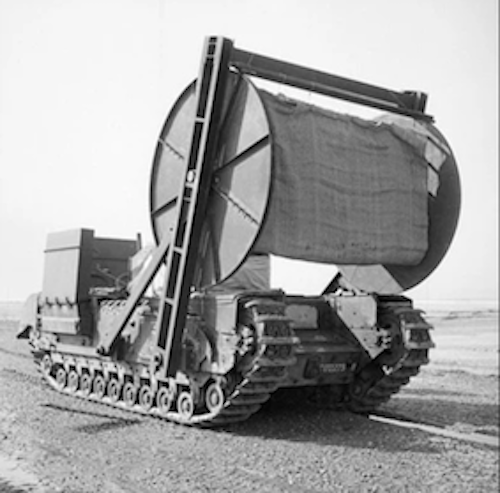
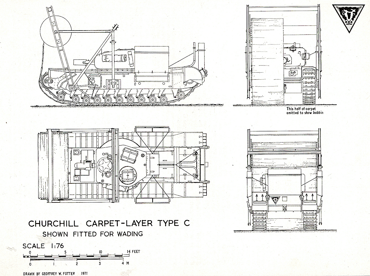
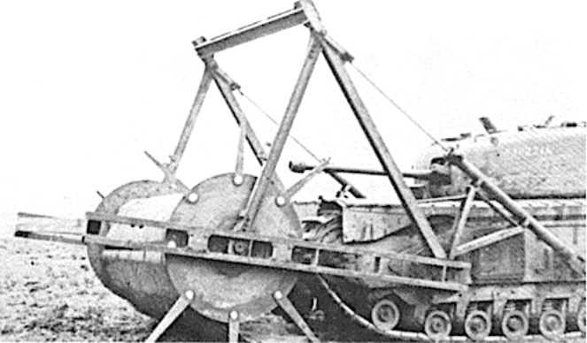
A special trials unit was formed by the 79th Armoured Division at Brancaster in Norfolk, where similar clay patches existed on the beach and after experimental work two forms of carpet-laying devices were developed which were eventually used with success on the Normandy beaches. These devices, which consisted of flexible carpeting wound on metal reels, were carried on special framework on the front of Churchill A.V.R.E.s and were designated Carpet-Layer (Type C) Mark II and Carpet-Layer (Type D) Mark Ill.
Both types of ‘Bobbins’, as these carpet-layers were commonly called, are shown on the scale drawings and feature in the following modelling article. A similar, though more simple, device had been used in the Dieppe raid but this, which consisted of a reel of hessian carpet carried on the front of a Churchill gun tank, was intended to be laid over barbed wire obstacles to enable these to be crossed by infantry and wheeled vehicles.
The carpeting used in conjunction with both the Type C and the Type D carpet-layers consisted of sheets of hessian reinforced with tubular steel scaffold tubes, although photographic evidence exists of one particular ‘Bobbin’ (this took part in the landings but was disabled before placing its carpet) which carried a carpet comprised of interlocking flexibly-hinged metal strips very similar to the flexible trackway in use with the British Army at the present time. On the ‘Bobbin’ arriving at the location where a carpet was required to be laid the end of the carpet was lowered in front of the A.V.R.E. which moved forward driving over the carpet which continued to unwind from the reel.
These carpets, which stood up fairly well to the movement of wheeled traffic over them but became badly damaged after being used by tracked vehicles, were used as a temporary expedient only, being replaced by perforated steel plating as soon as conditions on the beaches allowed. After the carpet had been laid the empty reel and supporting structure was jettisoned and the carrier vehicle, which was a standard Petard armed A.V.R.E., could operate in the normal A.V.R.E. role. Most ‘Bobbins’ were based on the Churchill IV A.V.R.E. with a cast turret and this is the version depicted on the scale drawings.
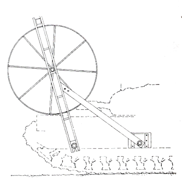
The Carpet-layer Type D was provided with a larger diameter reel than that of the Type C which enabled a longer length of carpeting to be carried. The Type [J reel was carried on a structure which was fixed to operate in one position (at high level over the forward end of the A.V.R.E.) but the structure fitted to the Type C was movable and allowed the carpet to unwind from the reel from a high position or alternatively from a low position just above the ground in front of the vehicle.
MODELLING CARPET LAYERS
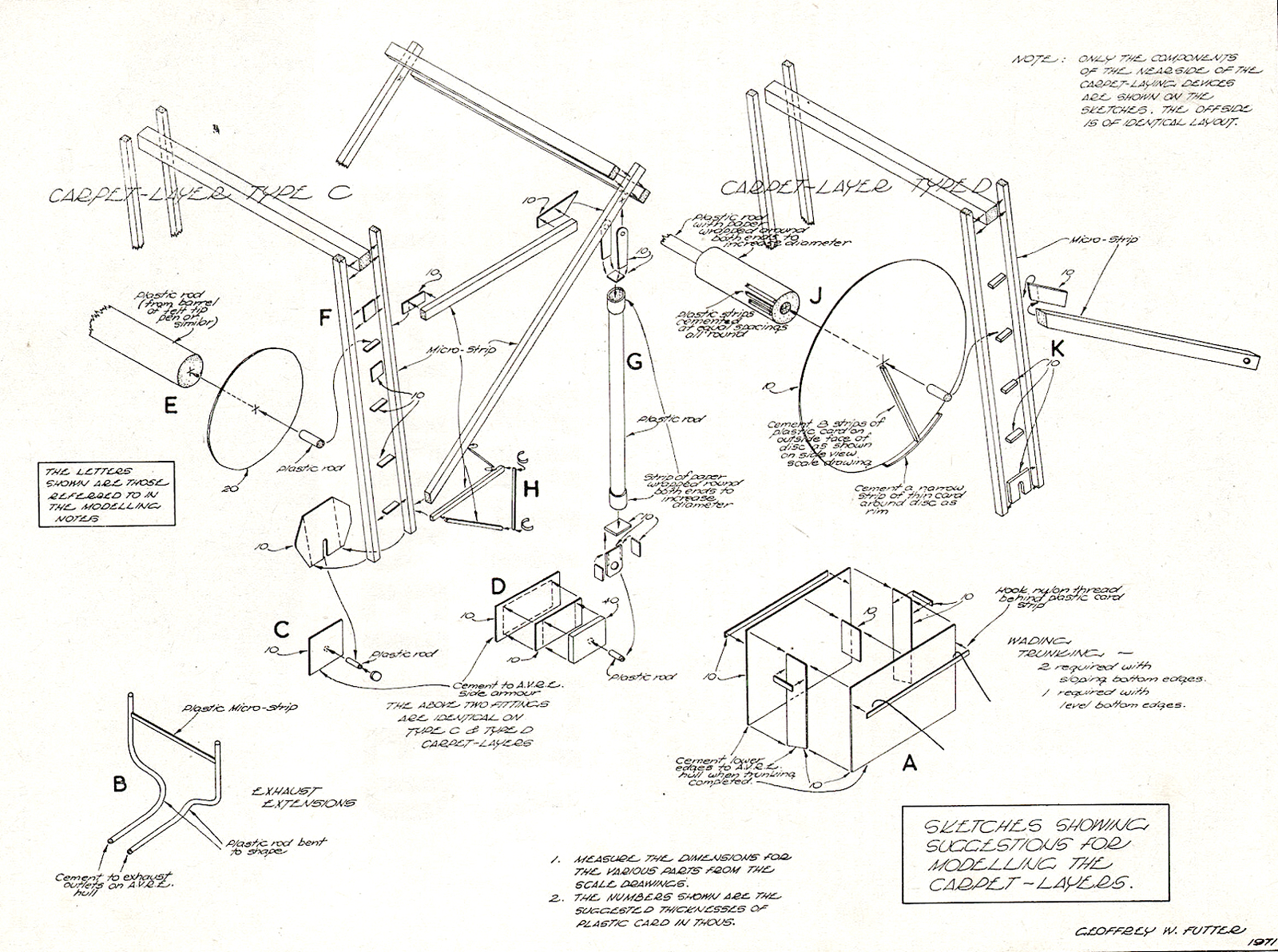
Stages One to Four inclusive apply to the modelling of component parts for both the Carpet-layer Type C and the Type D. The letters given in the notes show the particular sketch to be referred to. The correct size and shape of all the various parts required should be carefully measured or traced from the scale drawings.
STAGE ONE –
The A,V.R,E, model Prepare the 1 :76 scale Churchill A.V.R.E. model by converting the Airfix Churchill VII, as described in the May issue of ‘Military Modelling’, but when doing so, omit the special device attachment fittings on the side armour (which differ on the carpet-layers and are described later) and do not model the Churchill Ill turret. The fascine and frame are, of course, required.
STAGE TWO –
Churchill IV cast turret The turret provided with the Airfix Churchill VII kit can be adapted to represent the Churchill IV cast turret as the overall shape and size of these do not noticeably differ at 1 :76 scale. After the turret has been assembled, all corners should be rounded (with a file and then sanded} to give the appearance of the cast turret. The drawings and photographs give a clear indication of the finished profile required. The Petard mortar should be modelled as described in the May issue and on completion, can be cemented to the Airfix turret to replace the 75 mm. gun in the kit.
STAGE THREE –
Wading trunking and extended exhaust pipes From cut-out pieces of plastic card model the three lengths of wading trunking in the manner shown at A on the sketches and then cement these in position on the A.V.R.E. hull. Use fine nylon thread for the cables which support the trunkings and the sketches show how this thread can be joined to the trunking.
To fix the other ends of the three lengths of thread to the top of the hull make a hole (with a heated pin) on the longitudinal centre line of the hull between the engine covers and push the ends of the threads into the hole applying a dab of cement to hold them in position, ensuring when doing so that the threads will be as taut as possible after the cement has set. To represent the exhaust pipe extensions (illustrated at B) cut two pieces of SLATERS Microrod to the length required, carefully bending these to the shape shown on the drawings, and then cement the lower ends of the plastic rods on to the exhaust outlets on the top of the Airfix hull. The strut between the upper ends of the exhaust pipes can be a narrow strip of thin gauge plastic card with the ends cemented to the Micro-rod.
STAGE FOUR –
Device attachment fittings On both the Type C and Type D carpet-layers the fittings on the side armour for the attachment of the carpet reel supporting structures are of the same pattern and are also fitted in identical positions on both types. The sketches at C and D show clearly how these can be modified from short lengths of Microrod and cut-out pieces of plastic card.
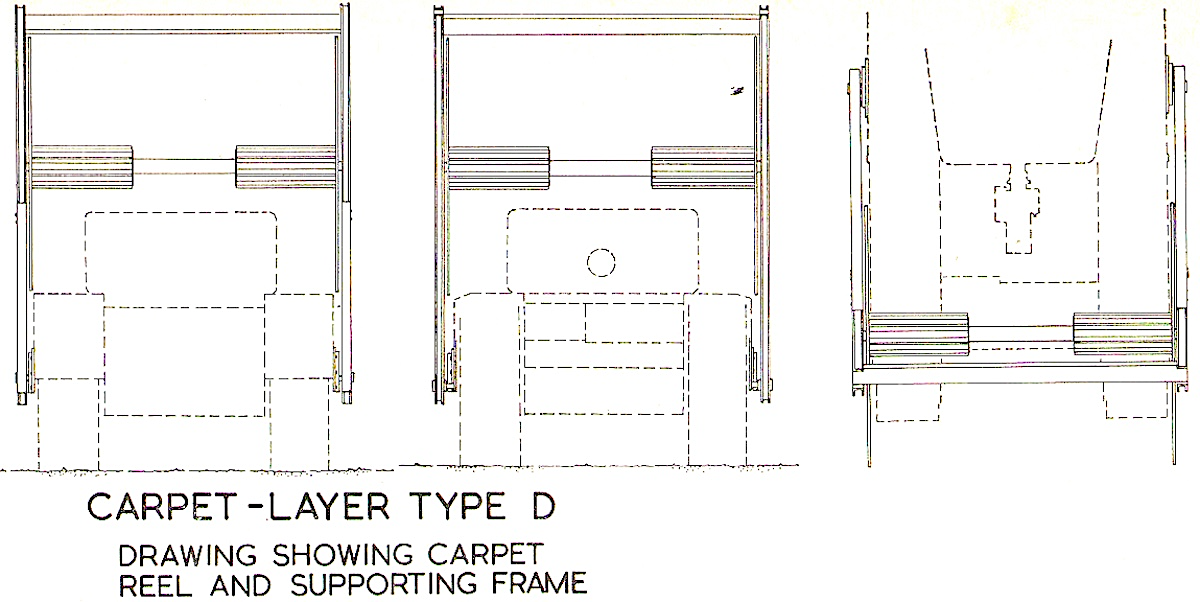
CARPET-LAYER TYPE D:
DRAWING SHOWING CARPET-REEL AND SUPPORTING FRAME
STAGE FIVE-
Type C carpet-laying device The sketch page shows in exploded form how the carpet reel ( E) and its supporting structure (F and G) can be modelled by using cut-out pieces of plastic card, plastic rod and plastic Micro-strip and if care is taken to ensure that all the parts required are of correct scale size and shape and are joined together at the proper positions and angles no problems should be encountered. The sketches and scale drawings show the Type C device in the elevated position as this is easier for modelling but, if the experienced modeller wishes, he cculd model this in the lowered position by using the respective photograph for guidance.
STAGE SIX-
Type D carpet-laying device As far as the modelling of this type is concerned the carpet reel (J) is more complicated than that of the Type C, but the supporting structure (K) will be more simple to model. It will be noted by referring to the drawings that the main arch of the structure is similar to that of the Type C except for the spacing pieces between the twin uprights which are located differently and also the shape of the plates at the lower ends of the uprights.
STAGE SEVEN –
Paint finish etc, The carpet-layers were painted overall in a khaki or earth colour – the normal colour of A.F.V.s of the period. The 79th Armoured Division emblem was stencilled on the front and rear of the hull and an Allied white star and ring was usually painted on the turret as shown on the scale top view.
STAGE EIGHT –
The carpeting The carpeting for both types can be comprised of two strips of thin buff coloured paper or cloth with lengths of Micro-rod cemented transversely between these at regular intervals. The strips of paper or cloth should not be cemented together face-to-face between the plastic rods. On the finished models the carpeting can be wrapped entirely around the reels or, alternatively, partially unwound to represent carpets in the process of being laid.
Reproduced with kind permission of Doolittle Media – originally published in Military Modelling October 1971
