Bill Hearne’s
WWI M/C COMBINATION
With the emergence of this new, exciting magazine [Military Modelling] one cannot help but imagine what it is likely to do to stimulate fresh interest amongst the already established military modelling fraternity and to what degree it will influence and encourage the yet un-addicted to the absorbing craft.
Letting the imagination run wild, one can envisage this new title of Military Modelling being snapped-up from newsagents throughout the English speaking world and the resulting clatter of scraping, sawing, filing and sanding and cutting, scoring, painting and sticking as millions concentrate on tiny, delicate things of plastic, metal and other materials as they put into practice selected suggestions found within these pages.
As a result of all this activity there will appear, sometime in the Spring perhaps, the fruits of this unbridled labour. Legions of little people regaled in gloriously coloured uniforms or drab khaki, standing, sitting, walking, mounted on horses, standing by, sitting in or sticking out of all manner of military machinery, engaged in or preparing for, combat. Not wishing to sound unjustifiably philosophical about our hobby, I do sometimes wonder what it is that motivates the modeller in his pursuit of modelling.
One obvious response to such a question must be, “Damn it man, it’s therapeutic for one thing. After a hard day at the office, factory, school or wherever, it propels one out of the commonplace and releases that latent artistic spirit one often needs to express”. True. And doubtless there are a million other individual reasons why the dedicated modeller, be he tiro or expert, jeopardises his social life, alienates wife or girlfriend to pore lovingly over an impassive piece of plastic or lead in an effort to bring life to it and bring about a miniature replica of something of the past or present.
It’s my opinion that there are two breeds of modeller. Firstly, the one who devotes his time and attention to a given era or period in history, who doesn’t go beyond the periphery and who, disappointingly I think, often cares not to show interest in other fields.
Secondly, there’s the modeller who, in effect, likes to keep on the move, periodically shifting his interest through the changing pattern of military development to seek new challenges, fresh outlets for his creative urge. The first type of modeller I believe is largely a student wishing to uncover time obscured information to incorporate his findings in exquisite, three-dimensional or flat figurines either individually, or through the medium of a diorama. Such study and dedication to purpose is to be greatly admired.
Personally, I see myself as fitting into the other category; the roving kind: since over the years that I’ve been hooked on modelling I’ve moved through quite a broad field of subject matter and worked in quite a range of materials. Static model aircraft of the Great War, cars, horse-drawn vehicles and military miniatures covering a number of periods. I‘ve done the things that I’ve wanted to do, am involved with the things
that I wish to be involved with and have a whole string of tentative ideas churning around in the back of my mind for future consideration. And all the while that nagging little question will recur, ‘Why am I doing it? However, the answer will doubtless continue to evade me and I’ll satisfy myself with excuses instead of reasons and I’ll continue to wonder what it is that motivates the modeller in his pursuit of modelling.
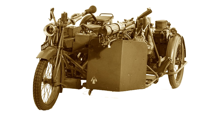
I suppose I shall never real/y know why one day I took myself and my camera to the Imperial War Museum to engage in taking pictures all around a beat-up, old motor cycle and sidecar which maybe did or possibly didn’t see some sort of service during the 1914-18 War. But take the photographs I did from all conceivable angles and at the same time, soaked up as much detail as possible to store in my mind’s eye for additional reference. I sought out all the old photographic material I could but found the pickin’s in this sphere a bit slim, albeit enough to get me started on the project, that of a motor cycle, machine-gun unit vehicle, fully equipped, as it would have gone to war, way back when.
The Motor Machine-Gun Corps made its appearance in 1915 after the then, military hierarchy came to the monumental decision that the Maxim type weapon had, grudgingly no doubt, a future in warfare: a fact hardened probably by the destructive manner in which the Germans used theirs. Following extensive W.D. tests a machine designed and built co-operatively by the Clyno Engineering Co. of Wolverhampton and Vickers Ltd. – Clyno providing the motor cycle and Vickers, the machine-gun supporting sidecar – was accepted and put into production.
The combination was furnished with three individual sidecar units, A, B and C. ‘A’ was the m.g. platform, ·s· a similar construction but designed specifically for the transporting of extra ammunition, spares and equipment, while ·c· was a straightforward passenger carriage. Primitive by today’s standards, in as much as although the machine gunner was partially protected by an armour plate at the front of the sidecar, the driver was exceptionally vulnerable while on the move
In the event of stationary attack or defence he joined the gunner in the sidecar to feed the ammo belt into the breach and so enjoyed some small measure of cover. Like a smart Indian putting paid to the cowboy’s capers in the movies by shooting a leading horse on the escaping stage coach, so seemingly would a well-placed bullet have brought a sudden halt to the peripatetic motor-cyclists. An additional armoured shield was supplied with the machine which was attached to the gun passing through it. However photographic investigation would suggest that this was generally discarded because, I would suspect, it hindered the gunner’s relationship of eye with his field of fire.
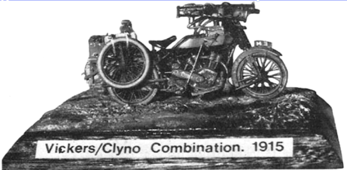
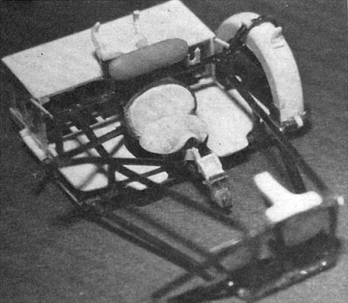
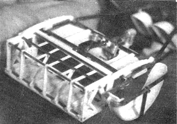
Above – Left and Right: Chassis assembly in the construction of Bill’s superb little model.
The sidecar was rigidly anchored to the motor cycle at four points for a strong assembly with the only seeming comfort for the gunner in the two heavy coil springs on his oversize, cycle-type seat. The sidecar was simply a tubular steel framework with mountings, one front, one rear, for the m.g. with the rear leg of its tripod fitting into a housing just below and in front of, the seat. Leaf springs either side of the frame extended from just in front and below the front of the rear wheels to a point mid-way of the bottom of the ammunition carrier on the back which also had a swinging arm arrangement either side at the top and was linked to the framework.
This carrier had provision for six ammo boxes in individual receptacles while, on a board across the top, there were three boxes set there for the purpose of holding spares, bits and pieces, oil and water for the gun, while spare petrol cans were lodged in convenient places.
The only protection for the crew against mud and water was in the form of a weatherproofed canvas sheet slung from the front of the motor cycle frame, across to the sidecar and underneath it. On the nearside of the gun carriage was strapped a convenient spade where also, obvious in photographs, was a rod affair with an oval handle: the use of which escapes me. Inside the frame at the front of the assembly were two, what one could only call, elongated buckets in a slightly, off vertical position, narrow_ at the tops, deep at the bottoms, into which the gunner put his feet. The machine-gun was the standard, field .303 piece mounted on an equally standard tripod which was normally carried in the forward position and locked on a T’ shape mount welded to the frame.
This mount also incorporated the retaining latches for the armour shield. The gun and tripod was carried with the front legs of the pod swivelled back and locked somewhere in-line with the rear one: the foot of which, as previously mentioned, was secured in a three-sided support just ahead of the seat. To the right of the gun was located a metal pannier, suspended from the m.c. frame beside the fuel tank across to the top of the sidecar frame, for an ammunition box. A like pannier was located to the rear of the sidecar between the mudguard top and the frame, convenient to the machine-gun mount there.
When going into action these panniers were furnished with ammo boxes which, with those stored in the carrier, gave a formidable supply of eight boxes. This capability to tote a load of ammunition, plus its speed and manoeuvrability, is what the brass appreciated and, despite their limited mention in W.W.1 histories, good use was made of them.
Their mobility made them ideal for infiltrating the enemy lines on scouting and skirmish operations. They were used to fill gaps in the line, hold positions and cover retreat when deemed necessary. Frequently they’d go to a position where the m.g. and tripod would be taken from the sidecar, carried and set-up on the ground, or wherever suitable for the action. A low silhouette tripod was strapped to the cooling jacket of the gun to permit its being taken from the regular tripod and used thus.
Saddles were heat moulded in 40 thou. card and I used 20 thou. for the foot buckets. To form the mudguards I found a suitable thickness hardwood – that is the cross-breadth of the guard – cut in width to slightly more than the outer diameter of the tyre, for curve front to back and, of an unimportant length – mine was about 4 in. long. One end I shaped a semi-circular form for the mud guard in profile and rounded this for the cross-section curve: a mudguard mould in effect.
The unworked end of the wood I clamped in a vice and, between two pairs of pliers, I heated over a flame a 1 in. wide strip of 40 thou. plastic card. When this became floppy I stretched it down. lengthwise on the mould and to a point slightly more than the required length I needed and held it for a second or two. After cooling I found the centre point of the semi-circle on the wood and, with the plastic still in place on it. scribed the guard edges on either side sufficiently to permit, when removed from the former, my snapping off the excess. When the end positions of the mudguards were established I cut off the additional material and cleaned up the plastic to a final finish. The front mudguard is different to the others and I made it from three pieces: the outer panel following the curve of the tyre and two sidewalls.
These I cemented together. It should be noted that the front forks. also the stirrup shaped, pedal bicycle type, front brake holder, with pads against the rim. pass through the mudguard and not to either side of it. The engine was made up from bits and pieces with resort to my favourite source for certain cylinders with fins. the hose from the Airfix, Dennis Fire Engine kit. Stretched sprue was utilized in the making of control wires. electrical leads and handle-bar levers. The machine-gun and tripods were all scratch built for the model as was the spade strapped to the side of the sidecar frame. The muddy battle bowler hanging from its handle was moulded in 20 thou. plastic card. ‘Buckles· for straps throughout were specially made in the same manner as I make coil springs, used on the saddles for example. The difference is square section, brass wire of small gauge instead of a needle or thicker, round wire for coils. Around the wire, held in a pin vice. I wrapped Slaters finest gauge rod in a tight spiral and then steamed it at the spout of a boiling kettle. For coils you cut across the spiral length after removal from the wire. For buckles, cut the length of the spiral in the centre of one side for individual, little squares. For the buckled strap impression, double a suitable width strip of 5 or 10 thou. plastic sheet, put one square over the rounded end and cement carefully with fluid cement. When hard dry, the strip ends are flattened in-line with the buckle.
The front wheel on the model is made steerable and was done this way. I drilled through a suitable gauge piece of sprue a hole large enough to take an extension of the S laters rod on the forks. The drilled piece was then attached to the appropriate position on the front of the frame and cemented. A ‘U’ form, which supports a horizontally project• ing spring of the suspension, had cemented between the walls of the figure a small, shallow, plastic washer: a washer in fact cut from the previously drilled sprue. When the rod was passed up, through the tube with the top of the forks . butted against its lower end, the washer in the ·u· was dropped over the top of the spindle rod and very carefully cemented to it.
Thus the front fork.s were able to turn on the frame. In commencing this description of the machine’s construction I said it was solely of plastic. Well I’m sorry, but I told a lie. In actual fact the ‘canvas’ weatherproofer around the underside of the sidecar was made from plastic solution impregnated handkerchief linen. Sorry about that. Painting of the model was no great trial and I used Humbrol ‘Authentic’ colours: khaki and matt black mixed with a touch of silver, with silver and brass used wherever applicable.
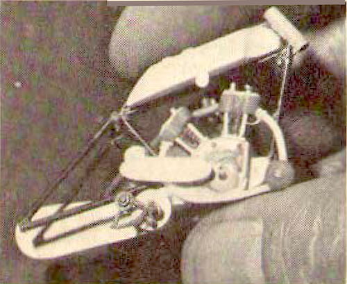
Above: The engine and engine frame of the model.
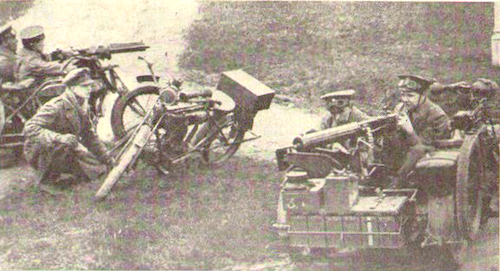
Above: An interesting illustration depicting members of the Motor Machine Gun Corps.
The Motor Machine-Gunners operated as separate batteries within the Corps. To the best of my knowledge a battery corn• prised the following. It centred on six, gun carrying combinations, backed by five identical machines but unarmed and presumably for replacement. Six ammo carrying combinations and one motor cycle with passenger sidecar for, I expect, officer transportation. With the exception of this latter, all the combinations carried two men. The C.O. had a staff car with a driver, with one officer responsible for two m.g. units and support mounted solo. There were four outriders on solo machines armed with rifles and three unmounted riflemen and one D.R. Additionally there were four motor vans doubtless for spares and repairs, with their drivers.
This complement was completed by three mechanics. My 1/30th scale replica of the Vickers-Clyno, m.g. carrying combination was constructed solely from plastic. The four tyres began life as curtain rings in a Woolworth’s store while Slaters finest gauge plastic rod furnished the spokes for the wheels – I’d refer you to the M.A.P. publication SCALE MODELS for December 1970 for a complete run-down on the making of scale, plastic wire wheels. Slaters 40 thou. rod was used in the making of the motor cycle and sidecar frames, while I put their microstrip to good use in the building of the rear mounted, ammunition carrier. The m.c. petrol/oil tank, ammo boxes, parts boxes, petrol can and pillion seat derived from 60 thou. plastic card and laminated to the required thicknesses.
Seats were leatherised with Track Colour and brown drawing ink and the tyres were done in dirty grey. After painting I ‘,gave the whole thing a satisfying ·splat· tering with my mixture of Artex/ Emulsion Glaze and paint ‘mud’ for an authentic, working vehicle appearance. It strikes me as a pity that one of the more progressive kit manufacturers have not come up with motor cycles and combinations so extensively used during two World Wars an’) the years between.
Tactically important, they have a place in many dioramas involving A.F.V.s. The sprightly B.S.A.s, Triumphs and Nortons of the British Forces. the husky Harleys of the U.S. Allies and the beefy B.M.W.s of Hitler’s gang. Indeed one American company has recently introduced a range of German mach• ines in 54 m.m. (1 /32nd) scale. But I think the types mentioned are sorely in need of representa• tion in the plastic medium in a scale or scales to delight the military modeller.
Maybe the inevitable wire wheels scare off the kit producers. But I think we’ve got that Iii’ problem licked (Scale Models December 1970) Granted we have on the market a number of large scale motor cycle kits by Revell, Pyro. Airfix and Italian companies but they’re of no use at all to the soldier buffs. Perhaps one day again or.e of the Japanese manu• facturers will see the need, jump in and sweep the market with a range of these, to be welcomed vehicles.
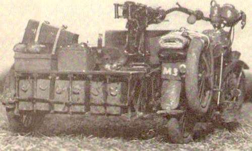
Above: Another fine shot of Heame’s master piece; note that the combination is
complete in every way right down to the last piece of carried equipment.
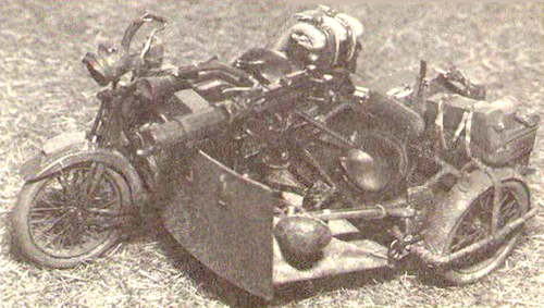
Above: The completed model has an incredible air of realism; readers fortunate enough to visit the 1971 M.E. Exhibition will have seen it in the flesh.
Reproduced with kind permission of Doolittle Media – originally published in Military Modelling 1971

